ENGINE PERFORMANCE
5.5L
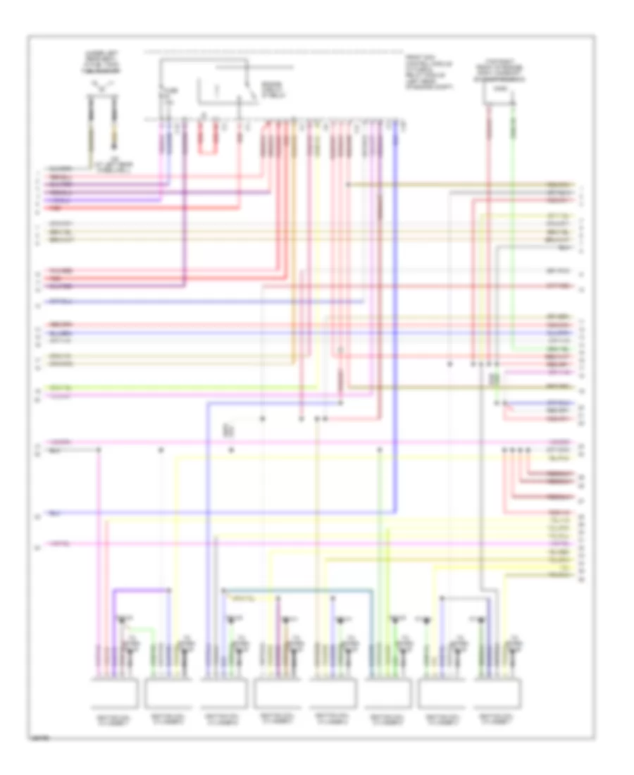
5.5L, Engine Performance Wiring Diagram (1 of 5) for Mercedes-Benz CLK550 2008

List of elements for 5.5L, Engine Performance Wiring Diagram (1 of 5) for Mercedes-Benz CLK550 2008:
- (left rear of engine compt) w16/5
- (not used)
- A p nmot
- A s 61
- A s aav
- A s ekpr
- A s hr
- A s slp1
- A s str1
- A t lues
- A t tev
- A u 5vg2f
- A u 5vsp
- Activated charcoal filter shutoff valve (in right rear wheelwell)
- Cabriolet
- Can-c-h
- Can-c-l
- Computer data lines system
- Coupe
- Diag
- E a dst
- E a sp1s
- E a sp2s
- E s 15
- E s kup1
- Electric suction fan engine & ac w/ integrated control (front of engine compt)
- Front prefuse box (right rear of engine compt)
- Fuel pump relay module
- Fuse 125a
- Fuse 200a
- Fuse 20a
- Fuse 60a
- Hot at all times
- Left fuel level sensor (under left rear seat, in fuel tank)
- M m es1
- M m es2
- M m es3
- M r senf1
- M r sp1
- M r sp2
- Me-sfi (me) control module (in front sam control module)
- Nca
- Pnk/red
- Purge control valve (left side of engine compt)
- Radio interference suppression capacitor 2
- Rear sam control module w/ fuse & relay module (left side of trunk)
- Red
- Right fuel level sensor (under right rear seat, in fuel tank)
- Terminal block (circuit 30)
- U u ubd
- U u ubre
- U u ubrm1
- W11w2
- W9 (left front of engine compt)
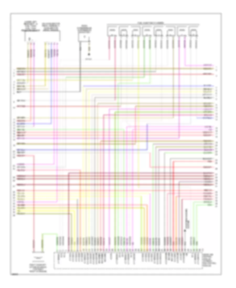
5.5L, Engine Performance Wiring Diagram (2 of 5) for Mercedes-Benz CLK550 2008
List of elements for 5.5L, Engine Performance Wiring Diagram (2 of 5) for Mercedes-Benz CLK550 2008:
- (top right front of engine) right camshaft exhaust solenoid
- (under left rear seat, in fuel tank) fuel pump (fp)
- C13
- C17
- C18
- Engine circuit 87 relay
- Front sam control module w/ fuse & relay module (left rear of engine compt)
- Fuse 15a
- Ignition coil cylinder 1
- Ignition coil cylinder 2
- Ignition coil cylinder 3
- Ignition coil cylinder 4
- Ignition coil cylinder 5
- Ignition coil cylinder 6
- Ignition coil cylinder 7
- Ignition coil cylinder 8
- Nca
- Pnk/red
- Red
- To spark plug
- W11w1
- W11w2
- W6 (at left rear wheelwell)
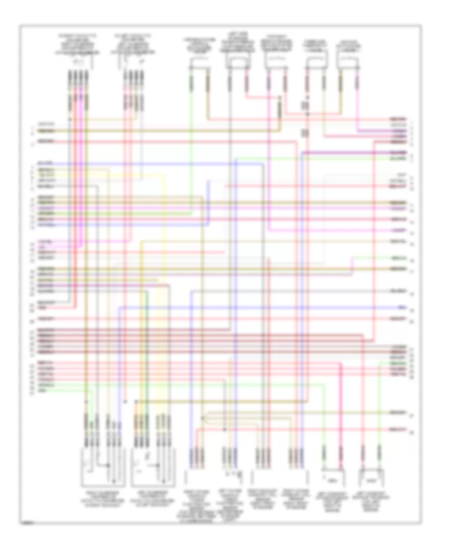
5.5L, Engine Performance Wiring Diagram (3 of 5) for Mercedes-Benz CLK550 2008
List of elements for 5.5L, Engine Performance Wiring Diagram (3 of 5) for Mercedes-Benz CLK550 2008:
- (on accelerator pedal assembly) accelerator pedal sensor
- (under left rear seat, in fuel tank) fuel tank pressure sensor
- A p zue1
- A p zue2
- A p zue3
- A p zue4
- A p zue5
- A p zue6
- A p zue7
- A p zue8
- A s dk
- A t eco
- A t lsh1hk
- A t lsh2hk
- A t lshvk1
- A t nwsa1
- A t nwse1
- A t nwse2
- A t su/suv
- A u 5vg1m
- A u 5vg2m
- A u lsu1vm
- A u lsu2vm
- A u uip
- E a lsh2hk
- E a lshk
- E a lsu1un
- E a lsu21a
- E a lsu2ip
- E a lsu2un
- E f nwga1
- E f nwga2
- Ev 2
- Ev 3
- Ev 4
- Ev 5
- Ev 8
- Ev1
- Fuel injector cylinders
- Lin
- M r hfm1
- M r ipm
- M r lsik
- M r senm1
- M r senm2
- Me-sfi (me) control module (in front sam control module)
- Radio interference suppression capacitor 1
- Red
- Right camshaft intake solenoid (top right front of engine)
- Sig
- Starting/charging system
- W11w1
5.5L, Engine Performance Wiring Diagram (4 of 5) for Mercedes-Benz CLK550 2008
List of elements for 5.5L, Engine Performance Wiring Diagram (4 of 5) for Mercedes-Benz CLK550 2008:
- (+)
- (-)
- (in left catalytic converter) left o2 sensor downstream of catalytic converter
- (in right catalytic converter) right o2 sensor downstream of catalytic converter
- (left side of engine) power steering pump pressure regulator valve
- (top right rear of engine) heating system shutoff valve
- Air pump switchover valve
- Left camshaft exhaust solenoid (top left front of engine)
- Left camshaft intake solenoid (top left front of engine)
- Left intake manifold tumble flap position sensor (center rear of engine compt)
- Left o2 sensor upstream of catalytic converter (in left exhaust)
- Nca
- Red
- Right exhaust camshaft hall sensor (right front of engine)
- Right intake camshaft hall sensor (right front of engine)
- Right intake manifold tumble flap position sensor (top center rear of engine, between cylinder banks)
- Right o2 sensor upstream of catalytic converter (in right exhaust)
- Sig
- Three disk thermostat valve
- Variable intake manifold switchover valve
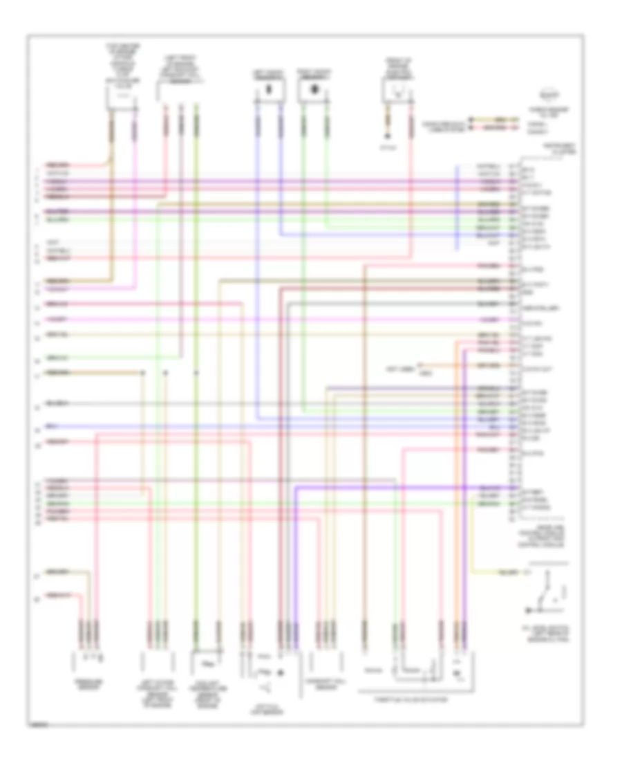
5.5L, Engine Performance Wiring Diagram (5 of 5) for Mercedes-Benz CLK550 2008
List of elements for 5.5L, Engine Performance Wiring Diagram (5 of 5) for Mercedes-Benz CLK550 2008:
- "check engine" mil ind
- (+)
- (-)
- (front of engine) electric air pump
- (left front of engine) left exhaust camshaft hall sensor
- (not used) x26/2
- (top center of engine) intake manifold tumble flap switchover valve
- A s hav
- A s slv
- A t dcm
- A t dcp
- A t kwths
- A t lshvk2
- A t nwsa2
- Agr steller1
- Camshaft hall sensor
- Can-b h
- Can-b l
- Computer data lines system
- Coolant temperature sensor (front of engine)
- E a ds
- E a ip1s
- E a ip2s
- E a ks1a
- E a ks1b
- E a ks2a
- E a ks2b
- E a lsu1ia
- E a lsu1ip
- E a tmot1
- E f kwga
- E f kwgb
- E f nwge1
- E f nwge2
- E f ref1
- E s fsoel
- Ev 6
- Ev 7
- Gnd
- Hot film maf sensor
- Instrument cluster
- Left intake camshaft hall sensor (left front of engine)
- Left knock sensor 2
- Me-sfi (me) control module (in front sam control module)
- Nw g a1
- Nw g a2
- O s kw out
- Oil level switch (left rear of engine oil pan)
- Pressure sensor
- Right knock sensor 1
- Sig
- Throttle valve actuator
- W11w1