AIR CONDITIONING
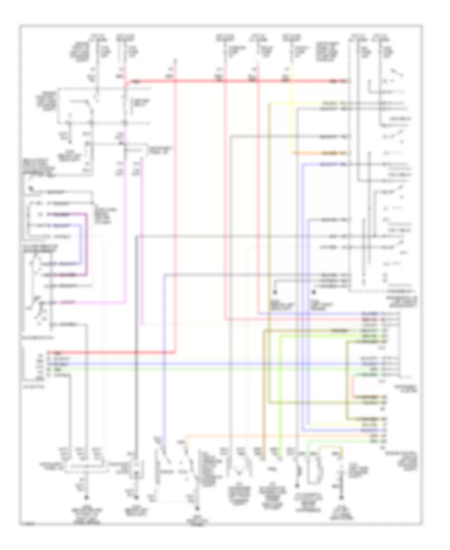
Air Conditioning Wiring Diagrams for Toyota Celica GT 2001
List of elements for Air Conditioning Wiring Diagrams for Toyota Celica GT 2001:
- (below right side of dash, in hvac housing) blower motor
- A/c
- A/c condenser fan motor (left front of engine compt)
- A/c evaporator temperature sensor (under right side of dash)
- A/c magnetic clutch & lock sensor (on a/c compressor)
- A/c switch
- A/c triple pressure switch (right front corner of engine compt)
- Blower resistor (in hvac housing)
- Blower switch
- C12
- C13
- Cds fuse 30a
- Def
- Dual
- Ecu-b fuse 7.5a
- Engine control module (left side of engine compt)
- Engine room j/b (left side of engine compt)
- Engine room r/b 1 (left side of engine compt)
- F28
- F30
- F31
- F32
- Fan 1 relay
- Fan 2 relay
- Fan 3 relay
- Fan rly fuse 5a
- G102 (left front fender)
- G106 (behind left headlight)
- G132 (on left cylinder head cover)
- G203 (right kick panel)
- G206 (behind center of dash, on right inst panel brace)
- Gnd
- Heater relay
- Hot at all times
- Hot in on or start
- Htr fuse 10a
- Htr fuse 50a
- I2 (dash harn, behind center of dash)
- Ig+
- Instrument cluster
- Instrument panel j/b
- Instrument panel j/b (right side of center console)
- J/c 2 (left side of engine compt)
- La/c
- M11
- M13
- Mg/c relay
- Off
- P10
- P17
- P18
- Radiator fan motor
- Rdi fuse 30a
- Red
- Single
- Warning fuse 5a
 English