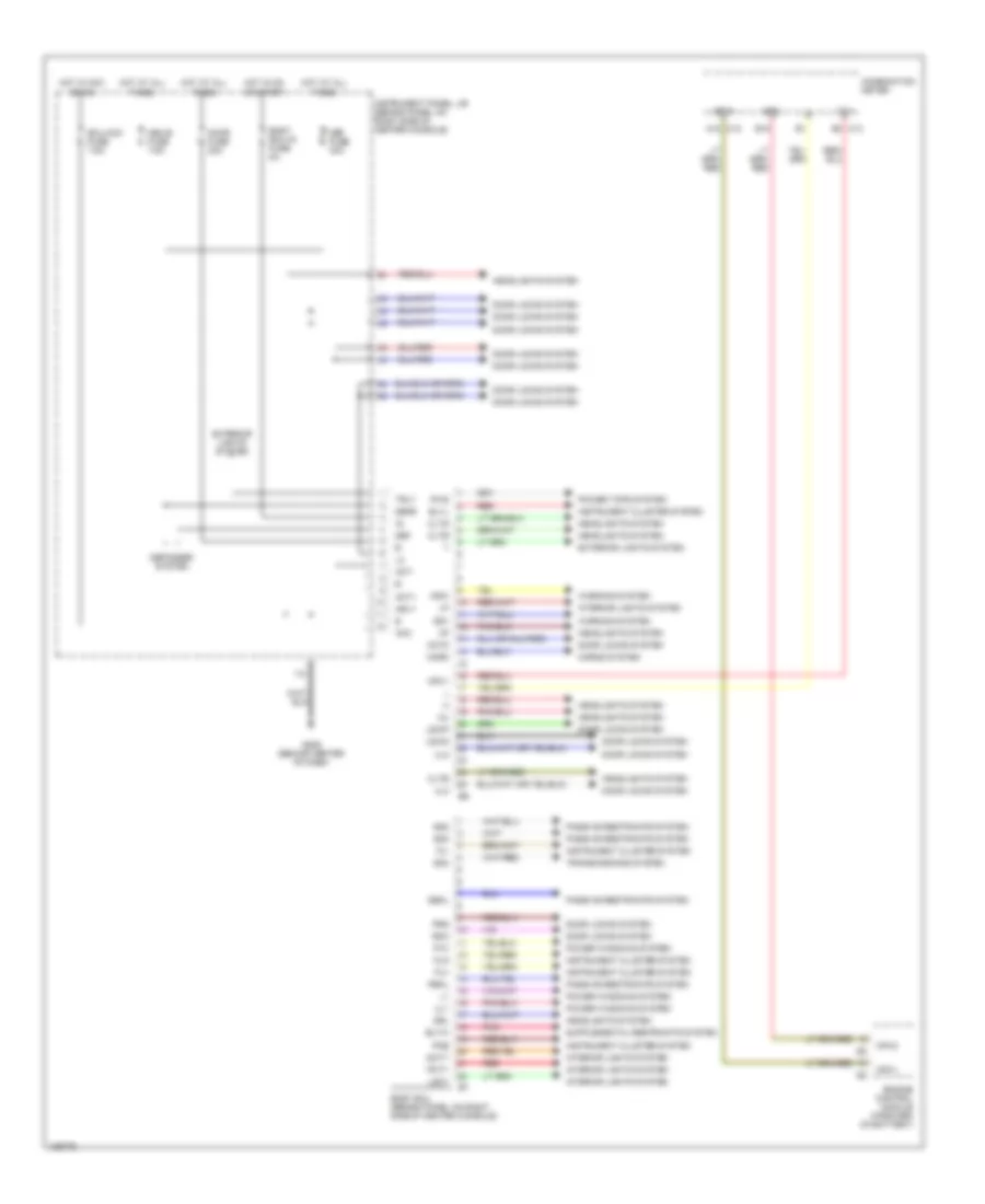
BODY COMPUTER
Body Computer Wiring Diagrams for Toyota Celica GT 2001
List of elements for Body Computer Wiring Diagrams for Toyota Celica GT 2001:
- Acc
- Act+
- Act-
- Actd
- B18
- Bltw
- Blvl
- Body ecu (behind panel on right side of center console)
- Body ecu-ig fuse 5a
- C12 a12
- C13 b3
- Cltb
- Clte
- Clts
- Combination meter
- Dbkl
- Dcty
- Def
- Def fuse 30a
- Defb
- Defogger system
- Door fuse 20a
- Door locks system
- Drl
- Ecu-acc fuse 7.5a
- Engine control module (forward of battery)
- Exterior lights system
- Fu+
- Fu-
- Fua
- G206 (behind center of dash)
- Headlights system
- Horn
- Horns system
- Hot at all times
- Hot in acc or on
- Hot in on or start
- Hrly
- I12
- Instrument cluster system
- Instrument panel j/b (behind panel on right side of center console)
- Interior lights system
- Ksw
- Lgcy
- Lswd
- Lswp
- Mbx-b fuse 7.5a
- Mpx+
- Mpx-
- Mpx1
- Mpx2
- P/w
- Passive restraints system
- Pbkl
- Pcty
- Pkb
- Pnk
- Power tops system
- Power windows system
- Prg
- Pws
- Rda
- Red
- Sg1
- Sg2
- Sg3
- Sg4
- Transmissions system
- Trly
- Tx+
- Ul1
- Ul2
- Ul3
- Warning system
 English