AIR CONDITIONING
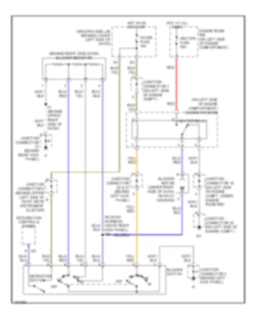
Heater Wiring Diagram, Double Cab for Toyota Tundra Limited 2004

List of elements for Heater Wiring Diagram, Double Cab for Toyota Tundra Limited 2004:
- (on left side of engine compt) engine room r/b 2
- (under right side of dash, on hvac housing) blower motor
- Behind upper right end of dash) i2
- Blower resistor (behind right side of dash)
- Blower switch
- Driver side j/b (under left end of dash)
- Engine room j/b (on left side of engine compt)
- Fusible link block (on left side of engine compt)
- Heater fuse 10a
- Heater fuse 50a
- Hot at all times
- Hot in on or start
- Htr relay
- J/c 35 (on left side of engine compt)
- J/c 58 (behind right side of dash)
- Off
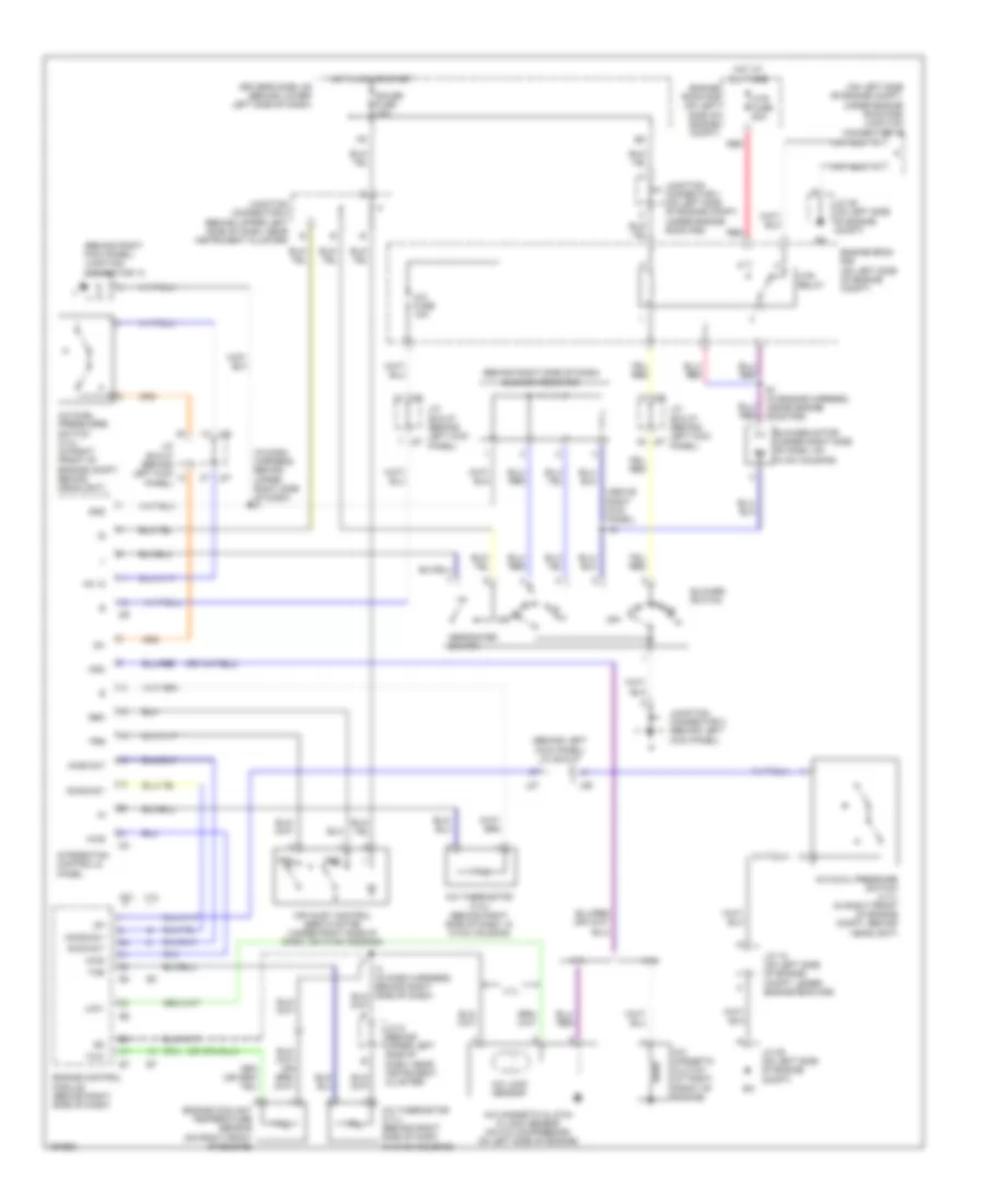
Heater Wiring Diagram, Standard Cab for Toyota Tundra Limited 2004
List of elements for Heater Wiring Diagram, Standard Cab for Toyota Tundra Limited 2004:
- (behind right side dash) blower resistor
- (in dash harness, above right kick panel) i16
- (on left side of engine compartment) engine room r/b
- Blower motor (under right side of dash, on hvac housing)
- Blower switch
- Defroster switch
- Driver's side j/b (behind lower left side of dash)
- Engine room r/b (on left side of engine compartment)
- Gauge fuse 10a
- Heater fuse 50a
- Heater relay
- Hot at all times
- Hot in on or start
- I25
- Integration control & panel
- Junction connector (behind right kick panel)
- Junction connector 1 (on left side of engine compt)
- Junction connector 18 (on left side of engine compt, under engine room r/b)
- Junction connector 25 (on left side of engine compt)
- Junction connector 26 & 27 (behind left kick panel)
- Junction connector 3 (behind left kick panel)
- Junction connector 8 (behind upper left side of dash, near instrument cluster)
- Off
- Red
- Side of dash)
Manual A/C Wiring Diagram, Access/Standard Cab for Toyota Tundra Limited 2004
List of elements for Manual A/C Wiring Diagram, Access/Standard Cab for Toyota Tundra Limited 2004:
- (above right kick panel) i16
- (behind left kick panel) j/c 26 & 27
- (behind right kick panel) junction connector 13
- (behind right side of dash) blower resistor
- (in dash harness, behind upper right side of dash) i4
- (on left side of engine compt, under engine room r/b) junction connector 18
- 3.4l
- 4.7l
- A/c dual pressure switch (4.7l) (in right front of engine compt, behind headlight)
- A/c duel pressusre switch (3.4l) (in right front of engine compt, behind headlight)
- A/c fuse 10a
- A/c lock sensor
- A/c magnetic clutch & lock sensor (on a/c compressor, on left side of engine)
- A/c magnetic clutch (at right front of engine)
- A/c thermistor (3.4l) (behind right side of dash, in hvac housing)
- A/c thermistor (4.7l) (behind right side of dash, in hvac housing)
- A/cs
- Ac +2
- Acid/act
- Acmg/ac1
- Aind/act
- Air inlet control servo motor (under right side of dash, on hvac housing)
- Blower motor (under right side of dash, on hvac housing)
- Blower switch
- Defroster switch
- Driver's side j/b (behind lower left side of dash)
- E1 (in engine harness, inside engine room r/b)
- Engine control module (behind right side of dash)
- Engine coolant temperature sensor (on right front of engine)
- Engine room r/b (on left side of engine compt)
- Frs
- Gauge fuse 10a
- Gnd
- Hot at all times
- Hot in on or start
- Htr fuse 50a
- Htr relay
- I24
- I25
- Ig+
- Integraton control & panel
- J/c 18 (on left side of engine compt, under engine room r/b)
- J/c 25 (on left side of engine compt)
- J/c 26 & 27 (behind left kick panel)
- J/c 9 (behind upper left side of dash, near instrument cluster)
- J26
- J27
- Junction connector 1 (on left side of engine compt, under engine room r/b)
- Junction connector 3 (behind left kick panel)
- Junction connector 8 (behind upper left side of dash, near instrument cluster)
- Lck1
- Mgc
- Off
- Rec
- Red
- The
- Thw
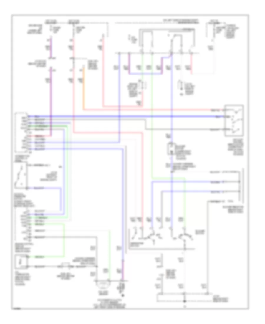
Manual A/C Wiring Diagram, Double Cab for Toyota Tundra Limited 2004
List of elements for Manual A/C Wiring Diagram, Double Cab for Toyota Tundra Limited 2004:
- (in dash harness, behind upper right end of dash) i1
- (on left side of engine compt) engine room r/b 2
- A/c
- A/c dual pressure switch (in right front of engine compt, behind headlight)
- A/c fuse 7.5a
- A/c lock sensor
- A/c magnetic clutch & lock sensor (4.7l: on a/c compressor, on left front side of engine)
- A/c thermistor (behind right side of dash, in hvac housing)
- A/cs
- Acld
- Acmg
- Air inlet control servo motor (under right side of dash, on hvac housing)
- B10
- Behind upper right end of dash) i2
- Blower motor (under right side of dash, on hvac housing)
- Blower resistor (behind right side of dash)
- Blower switch
- D10
- Def
- Defroster switch
- Driver side j/b (under left end of dash)
- Engine control module (behind right side of dash)
- Engine room j/b (on left side of engine compt)
- Frs
- Fusible link block (on left side of engine compt)
- Gauge fuse 15a
- Gnd
- Heater fuse 10a
- Heater fuse 50a
- Hot at all times
- Hot in on or start
- Htr relay
- I24
- I25
- Integration control & panel
- J/c 30 (on right front of engine compt)
- J/c 35 (on left side of engine compt)
- J/c 52 & 53 (behind center of dash)
- J/c 58 (behind right side of dash)
- J52
- J53
- Lcki
- Magnetic clutch
- Off
- Rec
- Sub j/b 3 (behind center of dash)
- Sub j/b 4 (behind center of dash)
- The