TRANSMISSION
3.4L
3.4L, 4WD Wiring Diagram for Toyota Tundra Limited 2004

List of elements for 3.4L, 4WD Wiring Diagram for Toyota Tundra Limited 2004:
- (a/t w/ vsc)
- (a/t w/o vsc)
- (a/t)
- (w/ vsc)
- (w/o vsc)
- 4wd
- 4wd fuse 20a
- 4wd ind
- A/t
- A/t p ind
- Abs actuator with ecu (right rear corner of engine compt)
- Acc fuse 15a
- Add actuator (front of engine)
- C11
- C12
- C14
- Combination meter
- Detection switch (4wd position) (transfer case)
- Detection switch (l4 position) (transfer case)
- Detection switch (neutral position) (transfer case)
- Diode (a/t) (behind upper left side of dash)
- Driver side j/b (lower left side of dash)
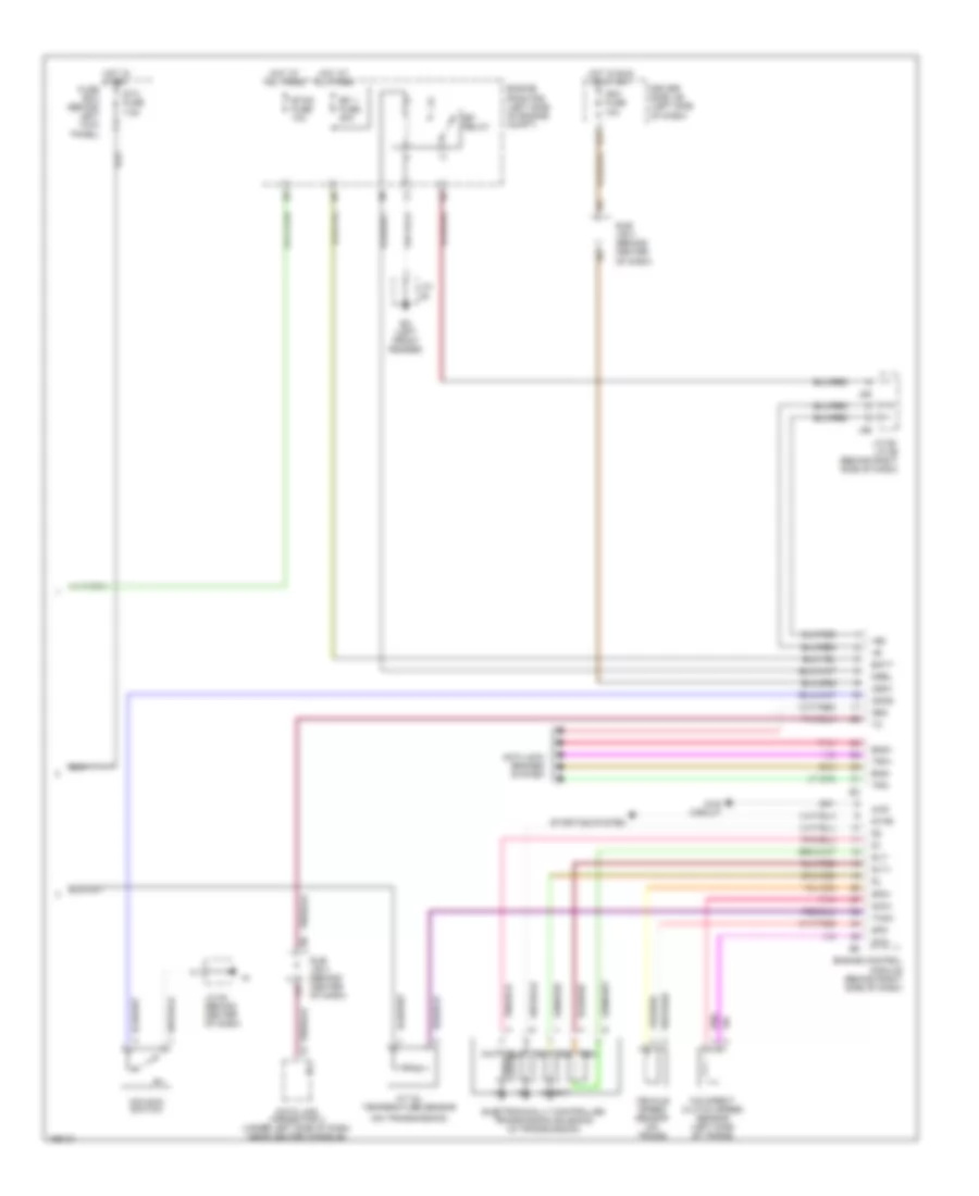
- Engine control module (behind right side of dash)
- Exi
- Exi4
- G11
- Gauge fuse 10a
- Hot in on or acc
- Hot in on or start
- J/c 10 (behind upper left side of dash)
- J/c 11 (behind upper right side of dash)
- J/c 12 (behind upper right side of dash)
- J/c 13 (right kick panel)
- J/c 28, j/c 29 (behind upper right side of dash)
- J/c 8 (behind upper left side of dash)
- J/c 9 (behind upper left side of dash)
- J28
- J29
- M/t w/ vsc
- M/t w/o vsc
- Neutral position switch (part of park/ neutral position switch)
- Red
- S17
- Skid control ecu (behind center of dash)
- Tfn
- Transmission control relay (behind lower right side of dash)
- W/ door lock ctrl
- W/o door lock ctrl
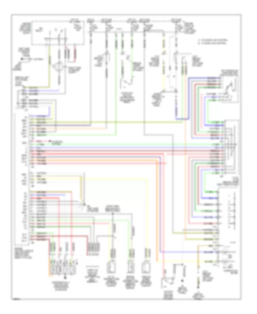
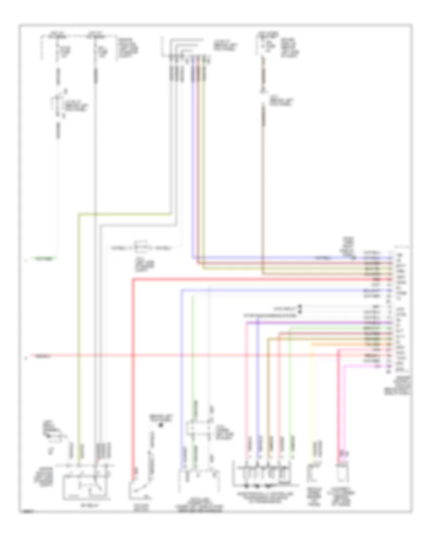
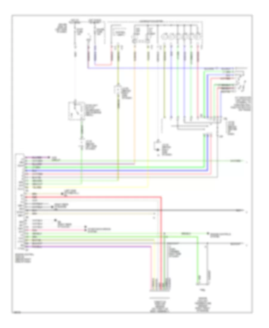
3.4L, A/T Wiring Diagram for Toyota Tundra Limited 2004
List of elements for 3.4L, A/T Wiring Diagram for Toyota Tundra Limited 2004:
- (behind left kick panel) j/c 26, j/c 27
- (behind upper left side of dash)
- (dash harn, behind right side of dash) i3
- (left side of engine compt) j/c 25
- (on transaxle) park/neutral position switch
- (right side of engine compt)
- A/t oil temp
- A/t oil temperature sensor (on trans- mission)
- Acc fuse 15a
- Batt
- C11
- C12
- C13
- C14
- Combination meter
- Diode (behind upper left side of dash)
- Driver side j/b (lower left side of dash)
- E01
- E02
- E03
- Ea (left front fender)
- Ed (left side of engine)
- Efi 1 fuse 15a
- Efi relay
- Electronically controlled transmission solenoids
- Engine control module (behind right side of dash, near "a" pillar)
- Engine coolant temperature sensor (front of engine)
- Engine room r/b (left side of engine compt)
- F11
- G11
- Gauge fuse 10a
- Hot at all times
- Hot in on or acc
- Hot in on or start
- Hot in start
- Ie (behind left kick panel)
- Ign fuse 5a
- Igsw
- Ih (behind right kick panel)
- J/c
- J/c 28, j/c 29 (behind upper right side of dash)
- J/c 4 (behind left kick panel)
- J/c 8 (behind upper left side of dash)
- J/c 9 (behind upper left side of dash)
- J26
- J27
- J28
- J29
- Me01
- Mrel
- No. 1
- No. 2
- No. 3
- Nsw
- O/d main switch (center of dash)
- O/d off
- Odlp
- Odms
- Oil
- Oilw
- Pnk
- Red
- Slt
- Slt+
- Slt-
- Sp1
- Sp2+
- Sp2-
- Sta
- Sta fuse 5a
- Starting system
- Stop fuse 15a
- Stoplight switch (on bracket, above brake pedal)
- Stp
- Throttle position sensor (on throttle body assembly)
- Thw
- Vehicle speed sensor (on trans- mission)
- Vta
- Vta2
- W/ door lock control
- W/o door lock control
4.7L
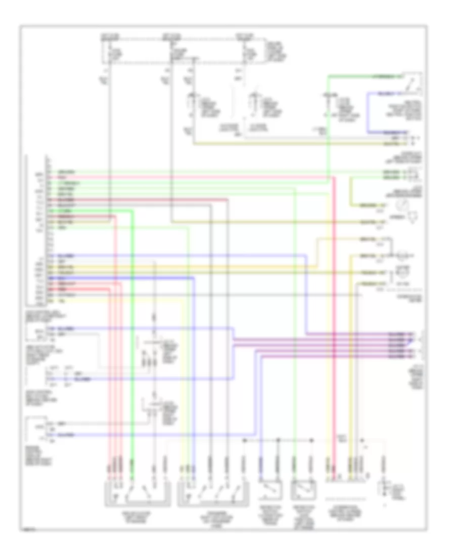
4.7L, 4WD Wiring Diagram, Access/Standard Cab for Toyota Tundra Limited 2004
List of elements for 4.7L, 4WD Wiring Diagram, Access/Standard Cab for Toyota Tundra Limited 2004:
- (a/t)
- (behind upper right side of dash)
- (m/t)
- 2-4
- 4hi ind
- 4lo ind
- 4wd
- 4wd control ecu (behind lower right side of dash)
- 4wd fuse 20a
- Abs actuator with ecu (w/o vsc) (right rear of engine compt)
- Acc fuse 15a
- Add
- Add actuator (left front of engine)
- C11
- C12
- C13
- C14
- Combination meter
- Detection switch (4wd position) (left side of trans)
- Detection switch (l4 position) (rear of trans)
- Diode (a/t) (behind upper left side of dash)
- Dl1
- Dl2
- Dm1
- Dm2
- Driver side j/b (lower left side of dash)
- Engine control module (behind right side of dash)
- Exi
- Exi4
- G j28
- G j29
- G11
- Gauge fuse 10a
- Gnd
- H-l
- Hot in on or acc
- Hot in on or start
- I24
- Ind1
- Ind2
- Integration control & panel (behind center of dash)
- J/c 10 (behind upper left side of dash)
- J/c 12
- J/c 13 (right kick panel)
- J/c 20 (behind upper right side of dash)
- J/c 28, j/c 29 (behind upper right side of dash)
- J/c 8 (behind upper left side of dash)
- J/c 9 (behind upper left side of dash)
- Neutral position switch (part of park/ neutral position switch)
- Pnk
- Red
- S17
- Skid control ecu (w/vsc) (behind center of dash)
- Spd
- Speedo
- Tl1
- Tl2
- Tl3
- Tm1
- Tm2
- Transfer shift actuator (on transfer case)
- W/ door lock ctrl
- W/o door lock ctrl
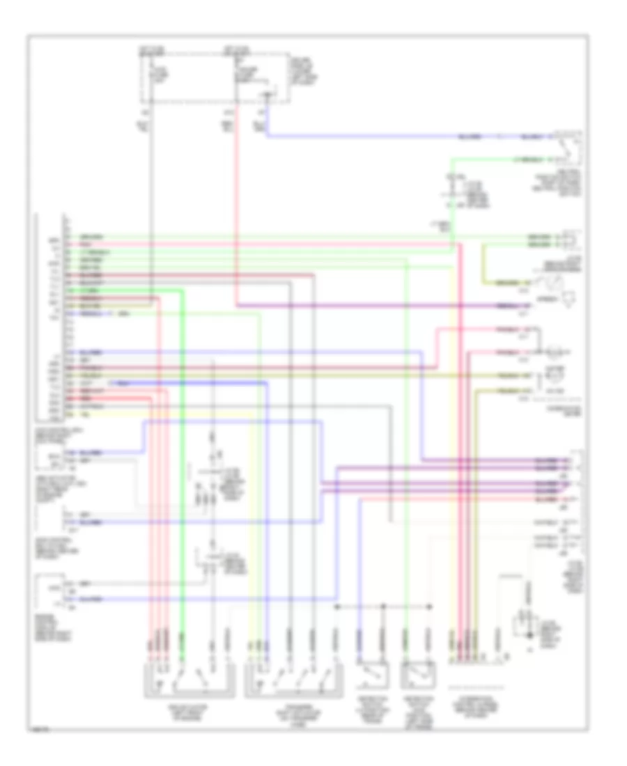
4.7L, 4WD Wiring Diagram, Double Cab for Toyota Tundra Limited 2004
List of elements for 4.7L, 4WD Wiring Diagram, Double Cab for Toyota Tundra Limited 2004:
- 2-4
- 4hi ind
- 4lo ind
- 4wd
- 4wd control ecu (behind right kick panel)
- 4wd fuse 20a
- Abs actuator with ecu (w/o vsc) (right rear of engine compt)
- Add
- Add actuator (left front of engine)
- C11
- C12
- C13
- C14
- Combination meter
- D12
- Detection switch (4wd position) (left side of trans)
- Detection switch (l4 position) (rear of trans)
- Dl1
- Dl2
- Dm1
- Dm2
- Driver side j/b (lower left side of dash)
- Engine control module (behind right side of dash)
- Exi
- Exi4
- G j28
- G j29
- Gauge fuse 15a
- Gnd
- H-l
- Hot in on or start
- I24
- I25
- Ind1
- Ind2
- Integration control & panel (behind center of dash)
- Ipo
- J/c 20 (behind center of dash)
- J/c 28, j/c 29 (behind center of dash)
- J/c 55 (behind right side of dash)
- J/c 55, j/c 56 (behind right side of dash)
- J/c 58 (behind right side of dash)
- J55
- J56
- Neutral position switch (part of park/ neutral position switch)
- Pnk
- Red
- S17
- Skid control ecu (w/vsc) (behind center of dash)
- Spd
- Speedo
- Tl1
- Tl2
- Tl3
- Tm1
- Tm2
- Transfer shift actuator (on transfer case)
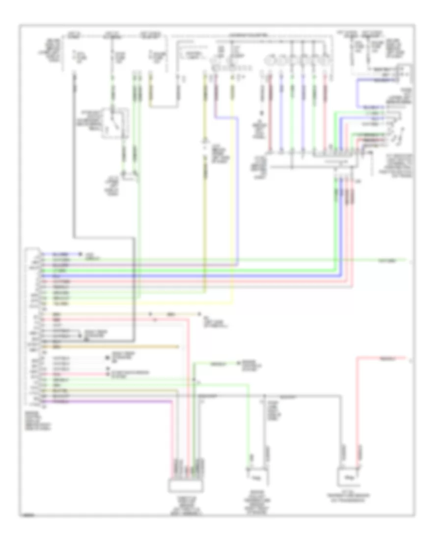
4.7L, A/T Wiring Diagram, Access/Standard Cab (1 of 2) for Toyota Tundra Limited 2004
List of elements for 4.7L, A/T Wiring Diagram, Access/Standard Cab (1 of 2) for Toyota Tundra Limited 2004:
- (dash harn right side of dash)
- (on transmission)
- (right rear of engine) eb
- +bm
- 4wd circuit
- A/t indicator light switch (integral to park/neutral position switch) (on trans)
- A/t oil temp
- A/t oil temperature sensor
- Acc fuse 15a
- C j/c 10 (upper left side of dash)
- C11
- C13
- C14
- Combination meter
- Control unit
- Diode (a/t) (upper left side of dash)
- Driver side j/b (behind left side of dash)
- Driver side j/b (behind lower left side of dash)
- E01
- E02
- E03
- Ec (left side of firewall)
- Engine control module (behind right side of dash)
- Engine controls system
- Engine coolant temperature sensor (right front of engine)
- G11
- Gauge fuse 10a
- Ge01
- Hot at all times
- Hot in run or acc
- Hot in run or start
- Hot in start
- Ie (behind left kick panel)
- J/c 28, j/c 29 (behind center of dash)
- J/c 9 (behind upper left side of dash)
- J28
- J29
- Me01
- Nsw
- O/d off ind
- Odlp
- Oilw
- Pnk
- Red
- Spd
- Sta
- Sta fuse 5a
- Starting/charging system
- Stop fuse 15a
- Stoplight switch (on bracket, above brake pedal)
- Stp
- Stsw
- Throttle position sensor (on throttle body assembly)
- Thw
- Vta1
- Vta2
4.7L, A/T Wiring Diagram, Access/Standard Cab (2 of 2) for Toyota Tundra Limited 2004
List of elements for 4.7L, A/T Wiring Diagram, Access/Standard Cab (2 of 2) for Toyota Tundra Limited 2004:
- (behind left kick panel) ie
- (dash harn right side of dash) i5
- (left front fender) ea
- +b2
- 4wd
- 4wd circuit
- Batt
- Data link connector 3 (under left side of dash, near center console)
- Driver side j/b (behind left side of dash)
- Efi 1 fuse 15a
- Efi relay
- Electronically controlled transmission solenoid (in transmission)
- Engine control module (behind right side of dash)
- Engine room r/b (left side of engine compt)
- Etcs fuse 10a
- F11
- Hot at all times
- Hot in run or start
- Ign fuse 5a
- Igsw
- J/c
- J/c 2 (left side of engine compt)
- J/c 26, 27 (behind left kick panel)
- J/c 4 (behind left kick panel)
- J/c 5 (upper left side of dash)
- J26
- J26 j/c 26, 27 (behind left kick panel)
- J27
- Mrel
- Nco+
- Nco-
- O/d direct clutch speed sensor (left side of trans)
- O/d main switch
- Odms
- Pnk
- Red
- Sil
- Slt
- Slt+
- Slt-
- Sp2+
- Sp2-
- Star
- Starting/charging system
- Thoc
- Vehicle speed sensor (on trans)
- Wfse
4.7L, A/T Wiring Diagram, Double Cab (1 of 2) for Toyota Tundra Limited 2004
List of elements for 4.7L, A/T Wiring Diagram, Double Cab (1 of 2) for Toyota Tundra Limited 2004:
- (left side of firewall) ec
- (right rear of engine) eb
- +bm
- 4wd circuit
- A/t indicator light switch (integral to park/neutral position switch) (on trans)
- A/t oil temp
- C11
- C13
- C14
- Combination meter
- Control unit
- D12
- Driver side j/b (left side of dash)
- E01
- E02
- E03
- Eb (right rear of engine)
- Engine control module (behind right side of dash)
- Engine controls system
- Engine coolant temperature sensor (right front of engine)
- Gauge fuse 15a
- Ge01
- Hot at all times
- Hot in run or start
- I3 (dash harness, right side of dash)
- Ipo
- J/c 28, j/c 29 (behind center of dash)
- J/c 45 (behind right side of dash)
- J/c 48 (behind left side of dash)
- J/c 55 (behind right side of dash)
- J28
- J29
- Me01
- Nsw
- O/d off ind
- Odlp
- Oilw
- Pnk
- Red
- Spd
- Sta
- Starting/charging system
- Stop fuse 15a
- Stoplight switch (on bracket, above brake pedal)
- Stp
- Stsw
- Throttle position sensor (on throttle body assembly)
- Thw
- Vta1
- Vta2
4.7L, A/T Wiring Diagram, Double Cab (2 of 2) for Toyota Tundra Limited 2004
List of elements for 4.7L, A/T Wiring Diagram, Double Cab (2 of 2) for Toyota Tundra Limited 2004:
- (on transmission)
- +b2
- 4wd
- 4wd circuit
- A/t oil temperature sensor
- Anti-lock brakes system
- Batt
- Data link connector 3 (under left side of dash, near center console)
- Driver side j/b (left side of dash)
- E17
- Ea (left front fender)
- Efi 1 fuse 20a
- Efi relay
- Electronically controlled transmission solenoid (in transmission)
- Eng+
- Eng-
- Engine control module (behind right side of dash)
- Engine room r/b (left side of engine compt)
- Etcs fuse 10a
- Fuse box (behind left kick panel)
- Hot at all times
- Hot in run or start
- Hot in start
- Ign1 fuse 10a
- Igsw
- J/c
- J/c 54 (behind center of dash)
- J/c 55, j/c 56 (behind right side of dash)
- J55
- J56
- Mrel
- Nco+
- Nco-
- Neo
- O/d direct clutch speed sensor (left side of trans)
- O/d main switch
- Odms
- Pnk
- Slt
- Slt+
- Slt-
- Sp2+
- Sp2-
- Sta fuse 7.5a
- Star
- Starting system
- Sub j/b 3 (behind center of dash)
- Thoc
- Trc+
- Trc-
- Vehicle speed sensor (on trans)