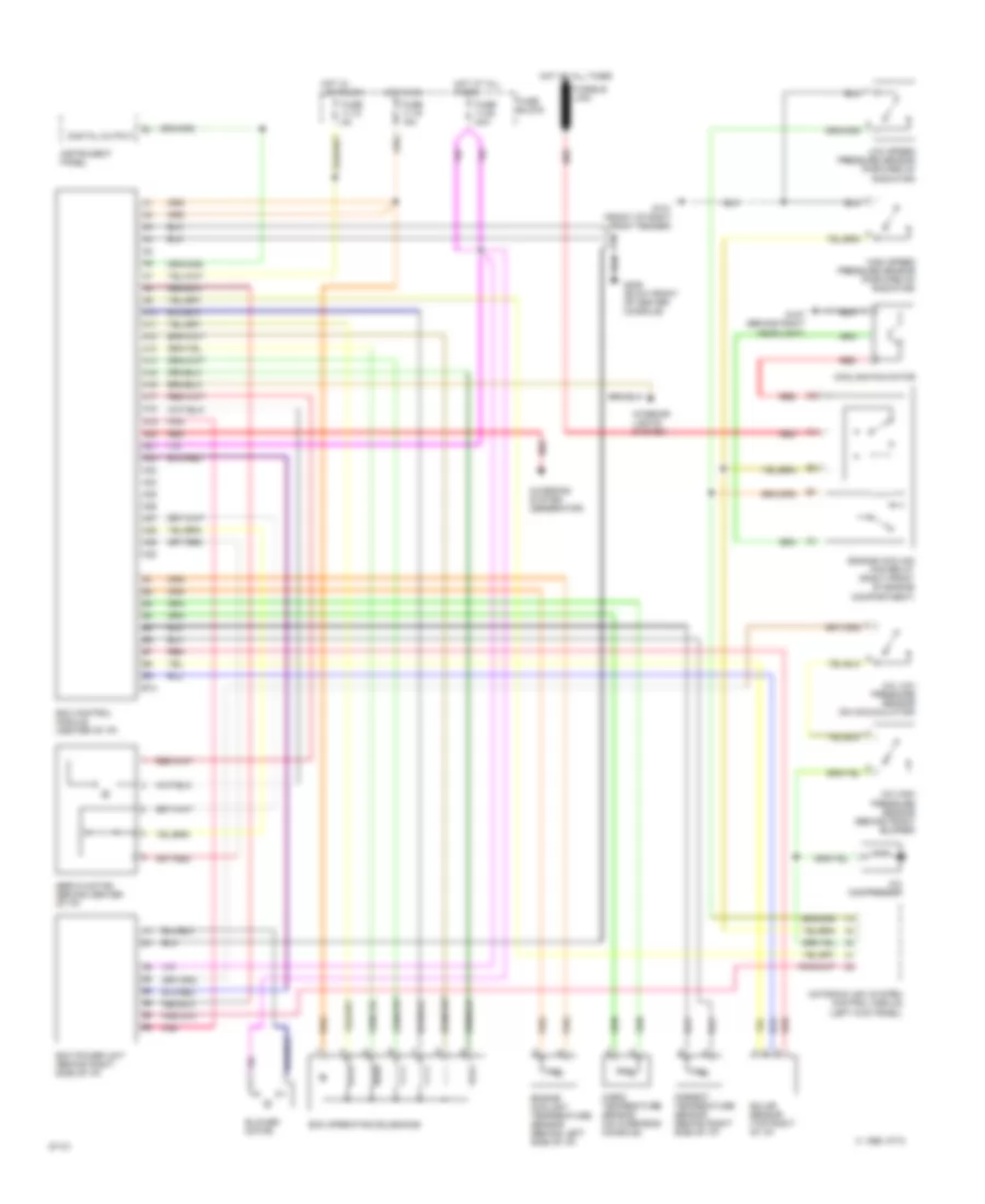
AIR CONDITIONING
Air Conditioning Wiring Diagrams for Volvo 960 1994
List of elements for Air Conditioning Wiring Diagrams for Volvo 960 1994:
- (left kick panel)
- A/c compressor
- A/c high pressure sensor (behind front bumper)
- A/c low pressure sensor (on accumulator)
- A10
- A11
- A12
- A13
- A14
- A15
- A16
- A17
- A18
- A19
- A20
- A21
- A22
- A23
- A24
- A25
- A26
- A27
- A28
- A29
- A30
- Ambient temperature sensor (behind right side of i/p)
- B10
- Blower motor
- C 1995 vftc
- Cabin temperature sensor (on overhead console)
- Charging system (generator)
- Cooling fan motor
- Digital output
- Ecc control module (center of i/p)
- Ecc operating solenoids
- Ecc power unit (behind right side of i/p)
- Engine coolant temperature sensor (behind left side of i/p)
- Engine cooling fan relay (right front of engine compartment)
- Fuse 11/10 5a
- Fuse 11/19 15a
- Fuse 11/28 30a
- Fuse block
- Fusible link
- G101 (front of right front fender)
- G107 (behind right headlight)
- G206 (blow front of center console)
- High speed pressure sensor (forward of radiator)
- Hot at all times
- Hot in on
- Hot w/ lights on
- Instrument panel
- Interior lights system
- Low speed pressure sensor (forward of radiator)
- Motronic (mfi) system control module
- Pnk
- Red
- Servo motor (behind center of i/p)
- Solar sensor (top right of i/p)
 English