ENGINE PERFORMANCE
2.9L
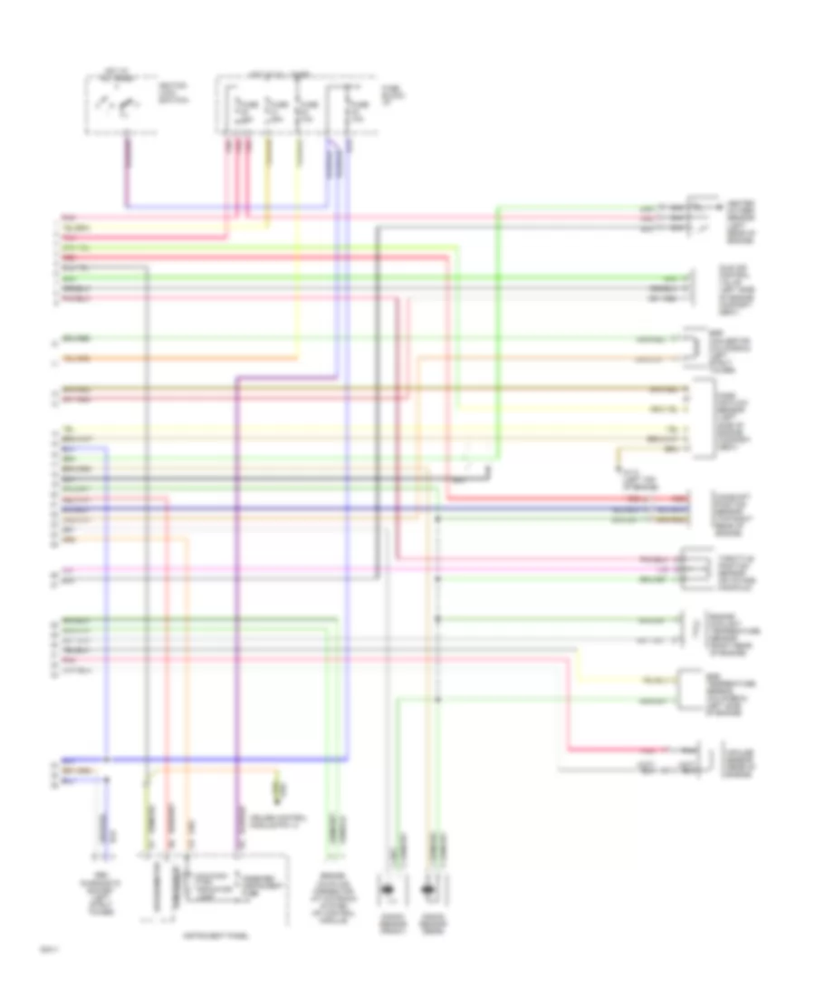
2.9L, Engine Performance Wiring Diagrams (1 of 2) for Volvo 960 1994

List of elements for 2.9L, Engine Performance Wiring Diagrams (1 of 2) for Volvo 960 1994:
- A/c high pressure sensor
- A/c solenoid coupling
- Battery
- Bus
- Ecc control module pin a9
- Ecc power unit pin b5
- Engine cooling fan relay pin b1
- Engine cooling fan relay pin b2
- Fuel injectors
- Fuel primer pump (in fuel tank)
- Fuel pump (left rear engine compt)
- Fuel pump relay
- G112 (left top of engine)
- G112 (lower left side of engine)
- G125 (left top of engine)
- G206 (behind center console)
- G408 (sedan) (trunk opening)
- G999 (wagon) (left tail light)
- High speed pressure sensor (eng cooling fan)
- Ignition coil relay (left front strut tower)
- Ignition coils
- Injectors relay (left front strut tower)
- Low speed pressure sensor (eng cooling fan)
- Motronic 1 power stage (on intake manifold)
- Motronic 2 power stage (on intake manifold)
- Motronic system mfi control module (under left dash)
- Nca
- Pnk
- Red
- Relay unit
- Service socket
- Spark plugs
- Timing control module (behind center of i/p)
2.9L, Engine Performance Wiring Diagrams (2 of 2) for Volvo 960 1994
List of elements for 2.9L, Engine Performance Wiring Diagrams (2 of 2) for Volvo 960 1994:
- Bridge coupling connector (at motronic system mfi control module)
- Camshaft position sensor (top right rear of engine)
- Combined instrument fuse
- Cruise control module pin 13
- Egr convertor (california) (left strut tower)
- Egr temperature sensor (california) (left side of engine)
- Engine coolant temperature sensor (right rear of engine)
- Fuse 10a
- Fuse 25a
- Fuse block: i/p
- G112 (left top of engine)
- Heated oxygen sensor (left rear of engine)
- Hot at all times
- Idle air control valve (left side of engine compart- ment)
- Ignition lock (switch)
- Iii
- Impulse sensor (rear of engine)
- Instrument panel
- Knock sensor (front)
- Knock sensor (rear)
- Malfunc- tion indicator lamp
- Mass air flow sensor (left side of engine compart- ment)
- Nca
- Obd diagnostic socket (left strut tower)
- Pnk
- Red
- Rpm sensor
- Speedometer
- Throttle position sensor (on intake manifold)