ANTI-LOCK BRAKES
Anti-lock Brakes Wiring Diagram (1 of 2) for Acura TSX 2005

List of elements for Anti-lock Brakes Wiring Diagram (1 of 2) for Acura TSX 2005:
- +b-fsr
- +b-mr
- Can-h
- Can-l
- Diag-k
- Fl +b
- Fl-gnd
- Fr +b
- Fr-gnd
- Fuse 17 30a
- Fuse 18 15a
- Fuse 18 40a
- Fuse 21 7.5a
- G203 (at right side of engine compt)
- G501 (behind left side of dash)
- Glat
- Gnd
- Hot at all times
- Hot in on or start
- Ig1
- Interior lights system
- Mr-gnd
- Pnk
- Red
- Rl +b
- Rl-gnd
- Rr +b
- Rr-gnd
- S-gnd
- Steering angle sensor (in steering column)
- Stra
- Strb
- Strz
- Svcc
- Tcs off switch light
- Under-dash fuse/relay box (behind left kick panel)
- Under-hood fuse/relay box (on left rear corner of engine compt, forward of strut tower)
- Vsa modulator- control unit (at right side of engine compt)
- Vsa off switch
- X34
- Yaw
- Yaw rate sensor (at left side of floor)
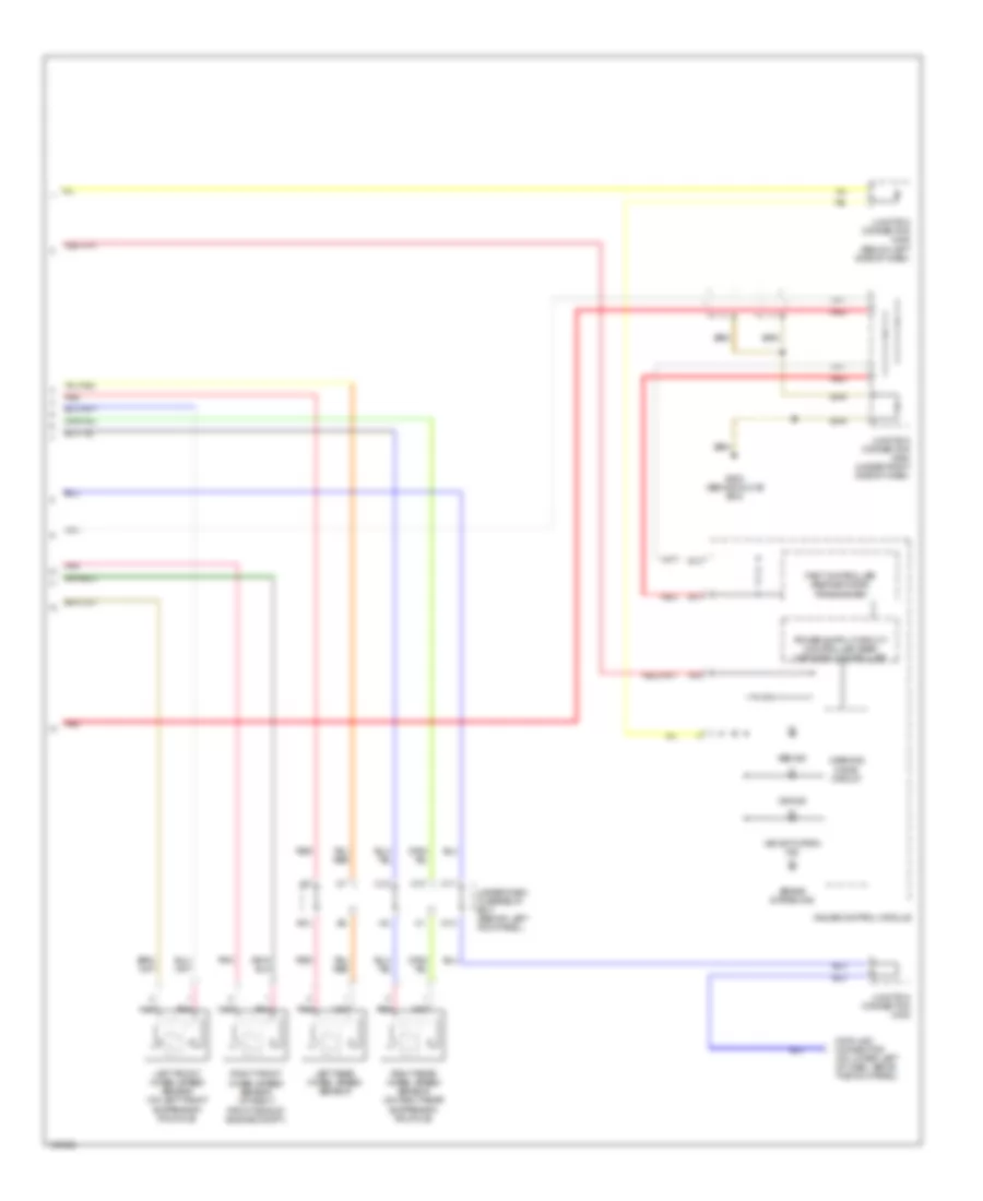
Anti-lock Brakes Wiring Diagram (2 of 2) for Acura TSX 2005
List of elements for Anti-lock Brakes Wiring Diagram (2 of 2) for Acura TSX 2005:
- A16
- Abs ind
- B12
- B13
- Brake system ind
- C10
- C11
- C12
- Data link connector (on lower left of dash, above the kick panel)
- E12
- Fast controller area network transceiver
- G503 (behind glove box)
- Gauge control module
- Junction connector c405
- Junction connector c406 (below left side of dash)
- Junction connector c554 (under right side of dash)
- Left front wheel speed sensor (on left front suspension knuckle)
- Left rear wheel speed sensor
- N13
- Pnk
- Red
- Right front wheel speed sensor (at right front side of engine compt)
- Right rear wheel speed sensor (on right rear suspension knuckle)
- Under-dash fuse/relay box (behind left kick panel)
- Vsa activation ind
- Vsa ind
- Warning drive circuit