COMPUTER DATA LINES
Data Link Connector Wiring Diagram for Acura TSX 2005

List of elements for Data Link Connector Wiring Diagram for Acura TSX 2005:
- (at left side of floor) g601
- (behind glove box) g503
- (behind left kick panel) under-dash fuse/relay box
- (dlc)
- (k-line)
- (mes)
- (scs)
- (wen)
- A24
- A25
- A26
- C11
- Chk in
- D10
- Data link connector (dlc) (at lower left of dash, above the kick panel)
- Diag +
- Diag -
- E23
- E29
- E30
- Ecm/pcm (under middle of dash)
- Fuse 8 15a
- G501 (behind left side of dash)
- G503 (behind glove box)
- Hot at all times
- Immobilizer control unit- receiver (in steering column cover)
- J/c c405 (behind left side of dash)
- J/c c407 (behind left side of dash)
- Mes connector
- Micu
- Multiplex control inspection connector
- N10
- N13
- N14
- Navigation service check connector (in trunk, under right side of rear shelf)
- Navigation unit (in trunk, under middle of rear shelf)
- P6 k- line
- Srs unit (behind middle of dash)
- Under-hood fuse/relay box (on left rear corner of engine compt, forward of strut tower)
- Vsa modulator control unit (at right side of engine compt)
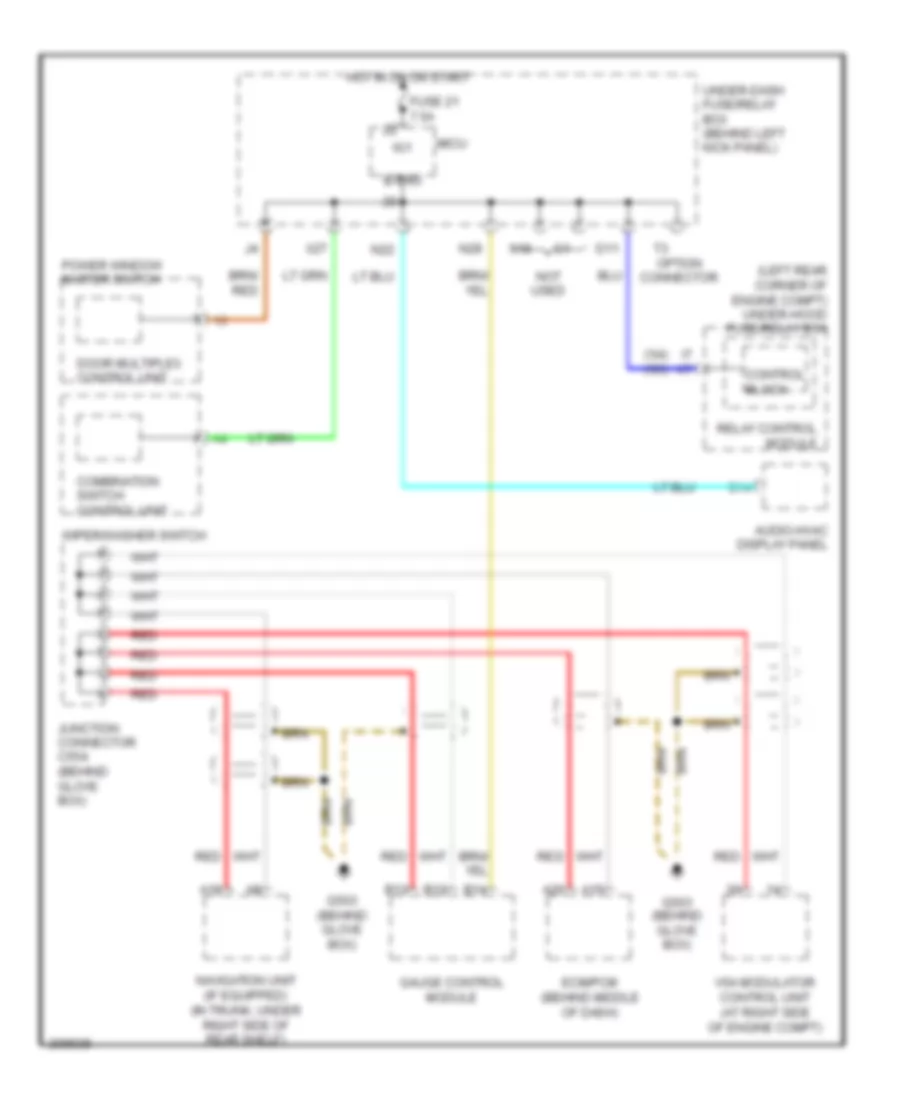
High/Low Bus Wiring Diagram for Acura TSX 2005
List of elements for High/Low Bus Wiring Diagram for Acura TSX 2005:
- ('04) ('05)
- (left rear corner of engine compt) under-hood fuse/relay box
- A15
- A18
- A26
- Audio-hvac display panel
- B-can
- B12
- B13
- B14
- Combination switch control unit
- Control block
- D11
- Door multiplex control unit
- Ecm/pcm (behind middle of dash)
- Fuse 21 7.5a
- G503 (behind glove box)
- Gauge control module
- Hot in on or start
- I7 k7
- Ig1
- Junction connector c554 (behind glove box)
- Micu
- N22
- N28
- Navigation unit (if equipped) (in trunk, under right side of rear shelf)
- Not used
- Option connector
- Power window master switch
- Red
- Relay control module
- Under-dash fuse/relay box (behind left kick panel)
- Vsa modulator control unit (at right side of engine compt)
- Wiper/washer switch
- X18
- X27