ANTI-LOCK BRAKES
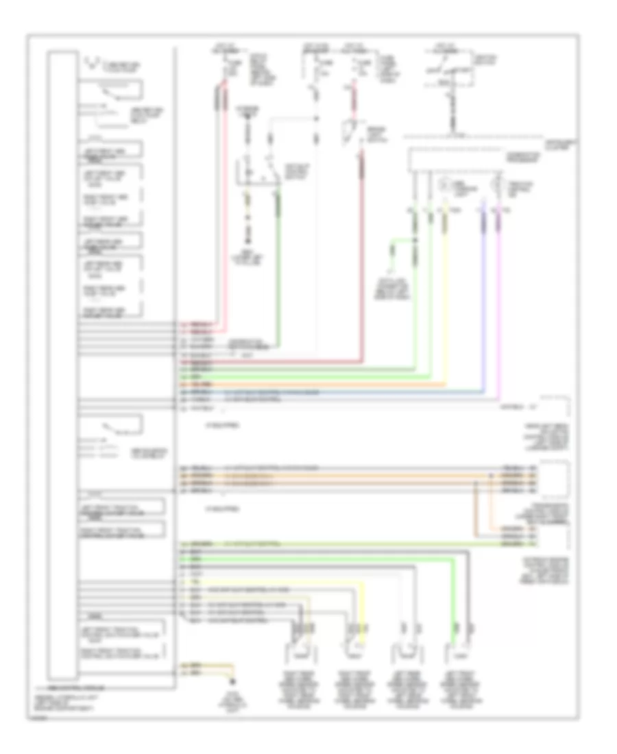
Anti-lock Brakes Wiring Diagram, with Electronic Stability Program (1 of 2) for Audi allroad Quattro 2001

List of elements for Anti-lock Brakes Wiring Diagram, with Electronic Stability Program (1 of 2) for Audi allroad Quattro 2001:
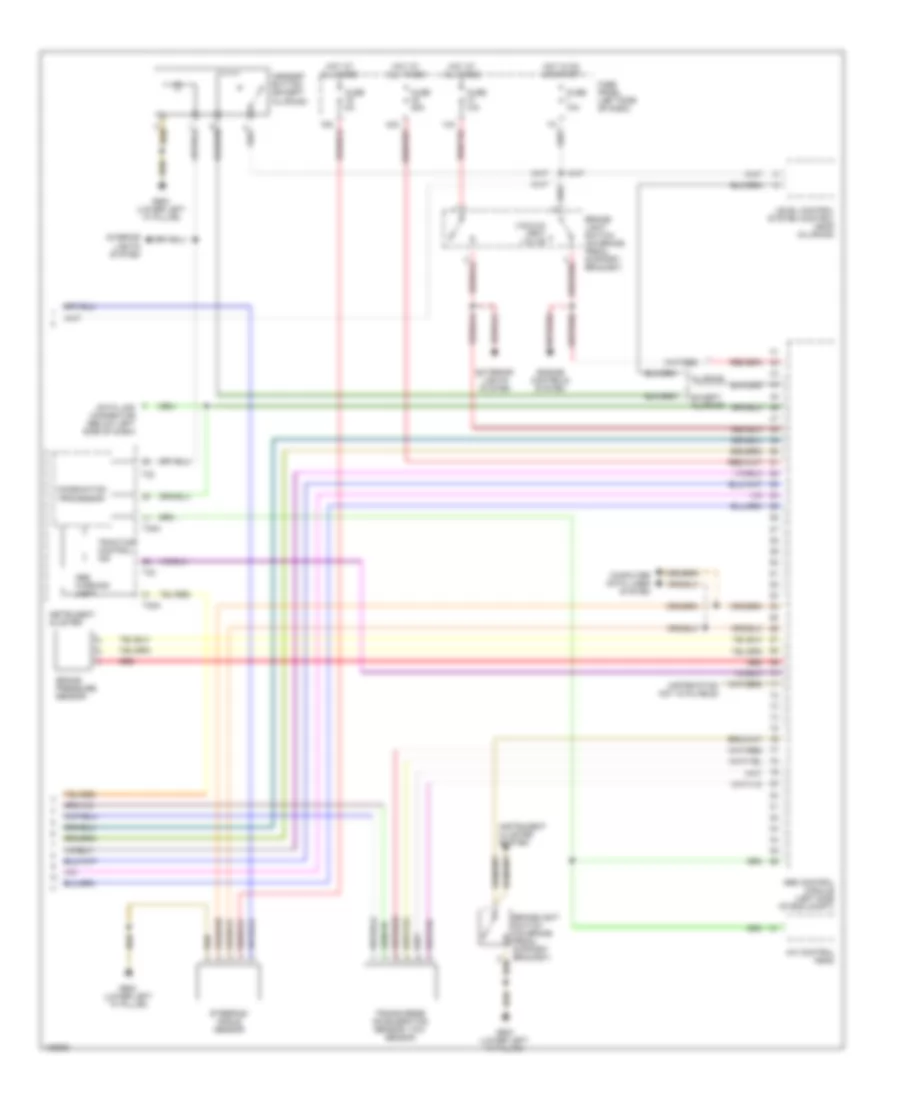
Anti-lock Brakes Wiring Diagram, with Electronic Stability Program (2 of 2) for Audi allroad Quattro 2001
List of elements for Anti-lock Brakes Wiring Diagram, with Electronic Stability Program (2 of 2) for Audi allroad Quattro 2001:
Anti-lock Brakes Wiring Diagram, without Electronic Stability Program for Audi allroad Quattro 2001
List of elements for Anti-lock Brakes Wiring Diagram, without Electronic Stability Program for Audi allroad Quattro 2001: