ANTI-LOCK BRAKES
Anti-lock Brakes Wiring Diagram (1 of 2) for Chevrolet Captiva Sport LT 2013

List of elements for Anti-lock Brakes Wiring Diagram (1 of 2) for Chevrolet Captiva Sport LT 2013:
- 5 volt reference
- Abs fuse 20a
- Abs fuse 50a
- Brake booster pump motor (near brake booster assembly)
- Brake booster pump motor relay
- Brake booster vacuum sensor (on brake booster assembly)
- Brake pressure modulator
- Brake vacuum sens sig
- Can bus high serial data
- Can bus low serial data
- Computer data lines system
- Electronic brake control module (ebcm) (near left front shock tower)
- G112
- G204 (left side of instrument panel)
- Hi spd data bus+
- Hi spd data bus-
- Hot at all times
- Left front wheel speed sensor (wss) (on left front wheel steering knuckle)
- Left rear wheel speed sensor (wss) (on left rear wheel hub)
- Lf wheel spd sens sig
- Lf wheel spd sens sply
- Low reference
- Lr wheel spd sens sig
- Lr wheel spd sens sply
- Nca
- Pnk
- Relay coil control
- Rf wheel spd sens sig
- Rf wheel spd sens sply
- Right front wheel speed sensor (wss) (on right front wheel steering knuckle)
- Right rear wheel speed sensor (wss) (on right rear wheel hub)
- Rr wheel spd sens sig
- Rr wheel spd sens sply
- Serial data comm
- Snsr sply
- Tan
- Underhood fuse block (left side of engine compt)
- Vac pmp fuse 20a
- X131
- X134
- X408
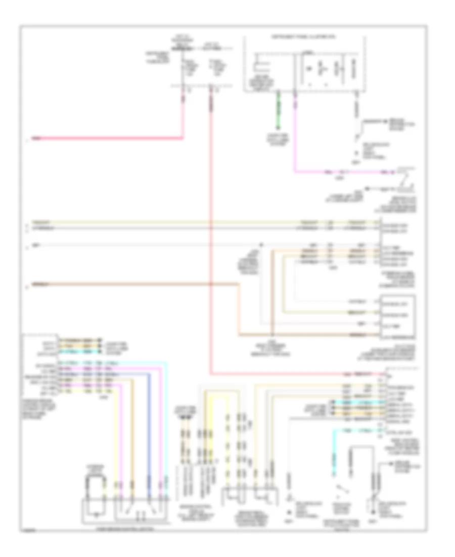
Anti-lock Brakes Wiring Diagram (2 of 2) for Chevrolet Captiva Sport LT 2013
List of elements for Anti-lock Brakes Wiring Diagram (2 of 2) for Chevrolet Captiva Sport LT 2013:
- Abs ind
- Bcm (stop) fuse 15a
- Body control module (bcm) (front of center floor console)
- Brake fluid level switch (on master brake cylinder reservoir)
- Brake ind
- Brake pedal position sensor (on brake pedal mounting arm)
- Can bus high
- Can bus low
- Computer data lines
- Computer data lines system
- Ctrl sw sig
- Data +
- Data -
- Data com
- Driver information center (dic) display
- Engine control module (2.4l: left rear of engine compt)
- Esc ind
- G201
- G401 (under left side of luggage compt)
- Ground distribution system
- Hot at all times
- Hot w/ run/crank relay energized
- Instrument panel cluster (ipc)
- Instrument panel fuse block
- Instrument panel i/p multi-function switch
- Interior lights system
- J339 (body harness, 35 cm from breakout for g302)
- J340 (body harness, 27 cm from breakout for g302)
- Logic
- Low ref
- Low reference
- Multi-axis acceleration sensor (under the floor console, at the park brake ratchet)
- Park brake control switch
- Parking brake control module (in front of left rear wheel on frame)
- Pnk
- Pos sens sig
- Release sw sig
- Run/ crank fuse 15a
- Sens low ref
- Sens sig
- Sens sply volt
- Serial data
- Serial data (+)
- Serial data (-)
- Serial data +
- Serial data -
- Signal gnd
- Splice block jx201 (right kick panel)
- Spy vol
- Steering wheel angle sensor (at base of steering column)
- Sw signal
- System
- Tan
- Tan l
- Traction control switch
- Vol ref
- Volt ref
- X108
- X200
- X405