SHIFT INTERLOCK
Ignition Lock Solenoid Wiring Diagram for Chevrolet Captiva Sport LT 2013

List of elements for Ignition Lock Solenoid Wiring Diagram for Chevrolet Captiva Sport LT 2013:
- Acc
- Body control module (bcm) (front of center floor console)
- Computer data lines system
- G201
- Hot at all times
- Hot w/ retained accessory power relay 1 energized
- Ign key resistor sig
- Ignition lock cylinder control solenoid (right side of steering column)
- Ignition switch
- Instrument panel fuse block
- J207
- Jx201 (right kick panel)
- Key capture fuse 10a
- Key-in switch
- Nca
- Off
- Park position switch
- Pwr/ moding fuse 2a
- Red
- Run
- Serial data bus+
- Serial data bus-
- Sig gnd
- Start
- Tan
- Transmission shift lever
- X210
- X314
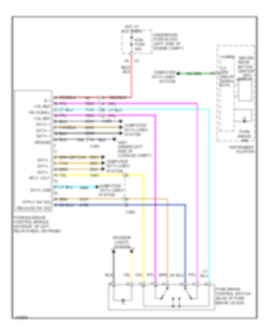
Park Brake System Wiring Diagram for Chevrolet Captiva Sport LT 2013
List of elements for Park Brake System Wiring Diagram for Chevrolet Captiva Sport LT 2013:
- (dic)
- (or tan)
- B +
- Computer
- Computer data lines
- Computer data lines system
- Data
- Data +
- Data -
- Data com
- Data lines
- Driver infor- mation center
- Epb fuse 40a
- G401 (under left side of luggage compt)
- Gmlan display serial
- Ground
- Hot at all times
- Instrument cluster
- Interior lights system
- L tan
- Logic
- Park brake control switch (base of park brake lever)
- Park brake ind
- Parking brake control module (in front of left rear wheel on frame)
- Release sw sig
- Spd
- Sply volt
- Sw signal
- System
- Underhood fuse block (left side of engine compt)
- Vol ref
- X405
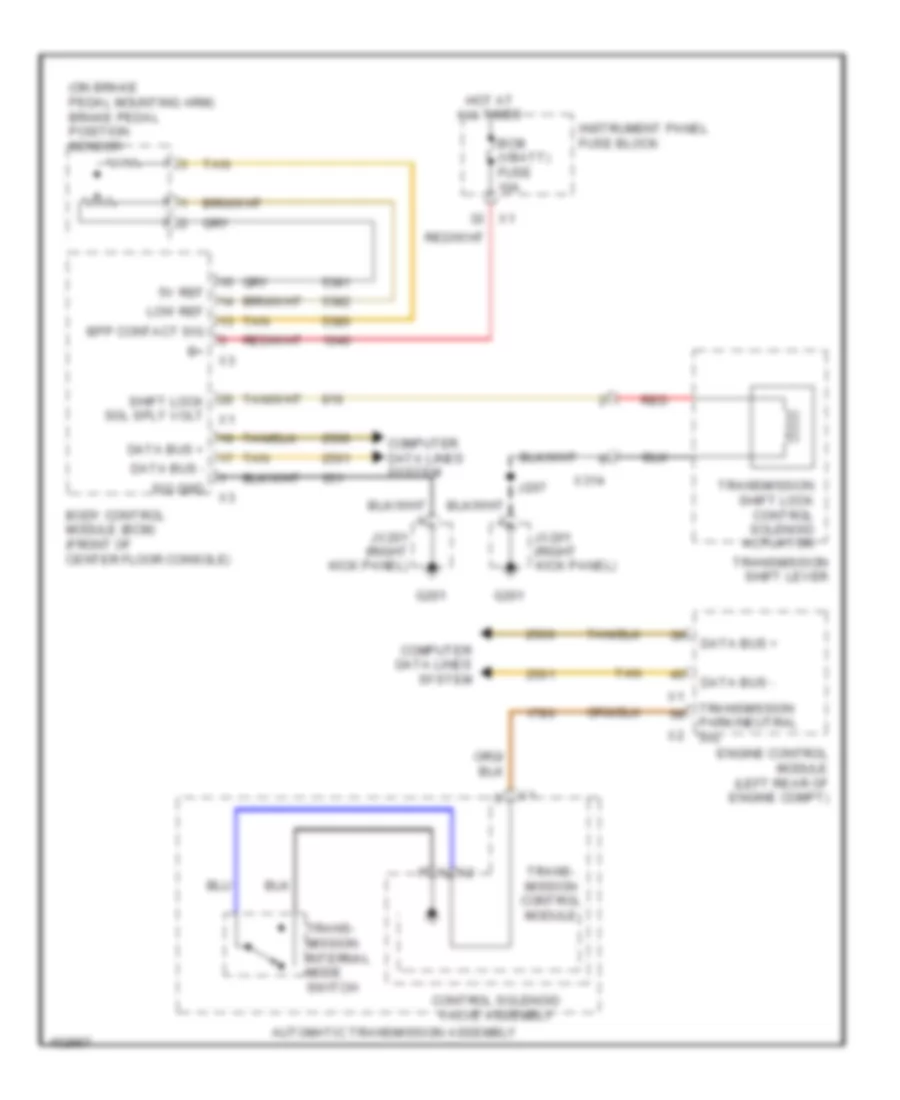
Shift Interlock Wiring Diagram for Chevrolet Captiva Sport LT 2013
List of elements for Shift Interlock Wiring Diagram for Chevrolet Captiva Sport LT 2013:
- (on brake pedal mounting arm) brake pedal position sensor
- 5v ref
- Automatic transmission assembly
- Bcm (vbatt) fuse 10a
- Body control module (bcm) (front of center floor console)
- Bpp contact sig
- Computer data lines system
- Control solenoid valve assembly
- Data bus +
- Data bus -
- Engine control module (left rear of engine compt)
- G201
- Hot at all times
- Instrument panel fuse block
- J207
- Jx201 (right kick panel)
- Low ref
- Red
- Shift lock sol sply volt
- Sig gnd
- Tan
- Trans- mission control module
- Trans- mission internal mode switch
- Transmission park/neutral sig
- Transmission shift lever
- Transmission shift lock control solenoid actuator
- X2 a
- X314