ANTI-LOCK BRAKES
Anti-lock Brakes Wiring Diagram (1 of 2) for Chevrolet Uplander LT 2006

List of elements for Anti-lock Brakes Wiring Diagram (1 of 2) for Chevrolet Uplander LT 2006:
- (lower left side of engine compt, on left strut tower) electronic brake control module (ebcm)
- 3.5l
- 3.9l
- 5v ref
- Abs fuse 13 10a
- Abs motor fuse 31 60a
- B + sol vlv ctrl
- B+ pump motor control
- Brake pressure modulator valve (bpmv)
- Class 2 ser data
- Computer data lines system
- Del torque sig
- G113 (at engine to transmission stud above g115)
- G115 (at engine to transmission stud nearest starter, below g113)
- Ground
- Hot at all times
- I/p fuse block (right side of dash, behind access panel)
- Ign 1 volt
- Ign main relay
- Lateral accelerometer signal
- Left front inlet
- Left front iso- lation (w/ tcs)
- Left front outlet
- Left front prime (w/ tcs)
- Left rear inlet
- Left rear outlet
- Lf wheel speed sens low ref
- Lf wheel speed sens sig
- Low ref
- Lr wheel speed sens low ref
- Lr wheel speed sens sig
- Pnk
- Powertrain control module (pcm) (3.5l) (left side of engine compartment, in air cleaner assembly) engine control module (ecm) (3.9l)
- Pump motor
- Req torque sig
- Req torque sig del torque sig
- Rf wheel spd sens sig
- Rf wheel speed sens low ref
- Right front inlet
- Right front iso- lation (w/ tcs)
- Right front outlet
- Right front prime (w/ tcs)
- Right rear inlet
- Right rear outlet
- Rr wheel spd sens sig
- Rr whl spd sen low ref
- S155
- Solenoid valves
- Steering wheel pos sig a
- Steering wheel pos sig b
- Tan
- Underhood fuse block (in underhood compartment, above right front wheel well)
- Yaw rate sen sig
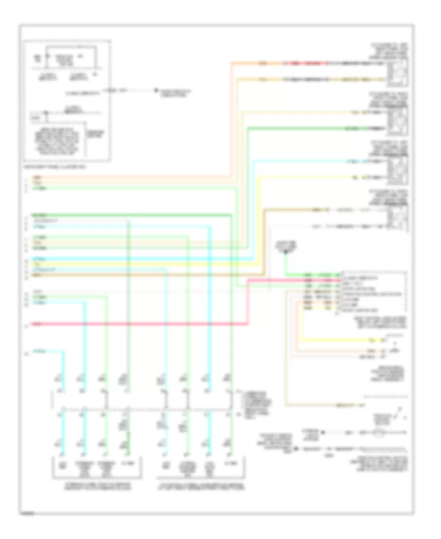
Anti-lock Brakes Wiring Diagram (2 of 2) for Chevrolet Uplander LT 2006
List of elements for Anti-lock Brakes Wiring Diagram (2 of 2) for Chevrolet Uplander LT 2006:
- (attached to left front wheel hub) left front wheel speed sensor (wss)
- (attached to left rear wheel hub)
- (attached to right front wheel hub) right front wheel speed sensor (wss)
- (attached to right rear wheel hub) right rear wheel speed sensor (wss)
- (on right side of dash support beam, above dash compartment) g200
- (or tan)
- 10v ref
- 5v ref
- Abs ind
- Body control module (bcm) (below left side of dash, left of steering column)
- Brake pedal position sensor (above brake pedal assembly)
- C1 underhood fuse block (in underhood compartment, above right front wheel c2
- Class 2 ser data
- Computer data lines system
- Ign 1 volt
- Instrument panel cluster (ipc)
- Interior lights system
- Lateral acceler- ometer sig
- Left rear wheel speed sensor (wss)
- Logic
- Low ref
- Message center
- Nca
- Pnk
- Red
- S255
- Service abs sys service stability sys service traction sys stability ctrl active stability ctrl off traction ctrl active traction ctrl off
- Steering wheel pos sig a
- Steering wheel pos sig b
- Steering wheel position sensor (near bottom of steering column)
- Stop lamp sw sig
- Stop lmp sw sig
- Tan
- Traction control off ind
- Traction control switch
- Traction control switch (center of i/p, next to driver information center (dic) display switch assembly)
- Traction control switch sig
- Well)
- Yaw rate & lateral acceleration sensor (at left front corner of right front floor)
- Yaw rate sen sig