SHIFT INTERLOCK
3.5L VIN L
3.5L VIN L, Shift Interlock Wiring Diagram for Chevrolet Uplander LT 2006

List of elements for 3.5L VIN L, Shift Interlock Wiring Diagram for Chevrolet Uplander LT 2006:
- (in dash harn, left side of dash) s048
- Air bag drive
- C-101
- C-211
- C-214
- C-26
- Center of dash)
- Combination meter
- Connector lock switch (connector coupled: on) (connector uncoupled: off)
- Cpu
- Data
- Data link connector (dlc) (partial) (under left side of dash)
- Detection circuit
- Engine compt relay box (left side of engine compt)
- Fuse 7.5a
- G8 (behind lower center of dash)
- Grd
- Hot at all times
- Hot in on or start
- Hot with taillight relay energized
- Indicator drive ckt
- Interface
- J/c 1
- J/c 3
- J/c 4
- Junction block (left end of dash)
- Off
- Passenger's side air bag off indicator light
- Passenger's side seat belt warning light
- Pnk
- Power
- Red
- S032 (in dash harn, center of dash)
- S088
- Side impact
- Srs ecu (under front of center console)
- Srs indicator
3.9L VIN 1
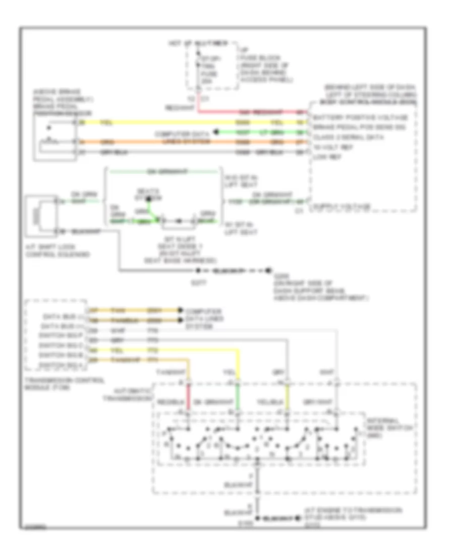
3.9L VIN 1, Shift Interlock Wiring Diagram for Chevrolet Uplander LT 2006
List of elements for 3.9L VIN 1, Shift Interlock Wiring Diagram for Chevrolet Uplander LT 2006:
- (above brake pedal assembly) brake pedal position sensor
- (at engine to transmission stud above g115) g113
- (behind left side of dash, left of steering column) body control module (bcm)
- 10 volt ref
- A/t shift lock control solenoid
- Automatic transmission
- Battery positive voltage
- Brake pedal pos sens sig
- Class 2 serial data
- Computer data lines system
- Data bus (+)
- Data bus (-)
- G200 (on right side of dash support beam, above dash compartment)
- Hot at all times
- I/p fuse block (right side of dash, behind access panel)
- Internal mode switch (ims)
- Low ref
- S155
- S277
- Seats system
- Sit n lift seat diode 1 (in sit-n-lift seat base harness)
- Stop/ trn fuse 20a
- Switch sig a
- Switch sig b
- Switch sig c
- Switch sig p
- Tan
- Transmission control module (tcm)
- W/ sit-n- lift seat
- W/o sit-n- lift seat