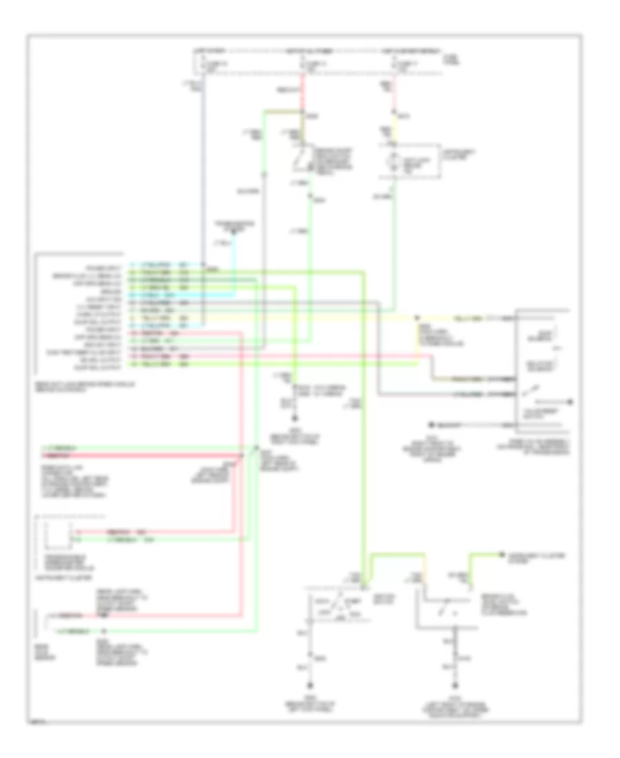
ANTI-LOCK BRAKES
Anti-lock Brake Wiring Diagrams for Ford Cab & Chassis F350 1997
List of elements for Anti-lock Brake Wiring Diagrams for Ford Cab & Chassis F350 1997:
- (main harn, left rear of engine compt)
- (rear lamp harn, near breakout to output shaft speed sensor) s429
- (w/o airbag) (w/ airbag)
- 4x4 input sig
- Acc
- Anti-lock brake ind
- Boo sw input
- Brake fluid level switch (on brake fluid reservoir)
- Brake fluid lvl sens (lo)
- Brake on/off (boo) switch (on bracket above brake pedal)
- Diag test/keep alive input
- Diff spd sens (hi)
- Diff spd sens (lo)
- Dump sol output
- Dump solenoid
- Fuse 13 15a
- Fuse 15 20a
- Fuse 17 10a
- Fuse panel
- G101 (right front of engine compartment, front of fender apron)
- G108 (left front of engine compartment, on upper radiator support)
- G200 (behind bottom of left kick panel)
- G203 (behind bottom of right kick panel)
- Ground
- Hot at all times
- Hot in run
- Hot in start or run
- Ignition switch
- Instrument cluster
- Instrument cluster system
- Iso sol output
- Isolation solenoid
- Lock
- Nca
- Off
- Power input
- Programmable speedometer/ odometer module
- Rabs data link connector (all gasoline: left rear of engine compartment) (7.3l diesel: behind lower center of dash)
- Rabs valve assembly (on frame rail, near front of transmission)
- Rear anti-lock brake (rabs) module (behind glove box)
- Rear axle sensor
- Red/pnk
- Run
- S102
- S202
- S215
- S216 s258
- S220
- S228 (main harn, in breakout to rabs module)
- S236
- S240
- S247 (main harn, left rear of engine compt)
- S248
- S428 (rear lamp harn, near breakout to output shaft speed sensor)
- Start
- Transmissions system
- Valve reset switch
- Vlv reset input
- Warn lp output
 English