ANTI-LOCK BRAKES
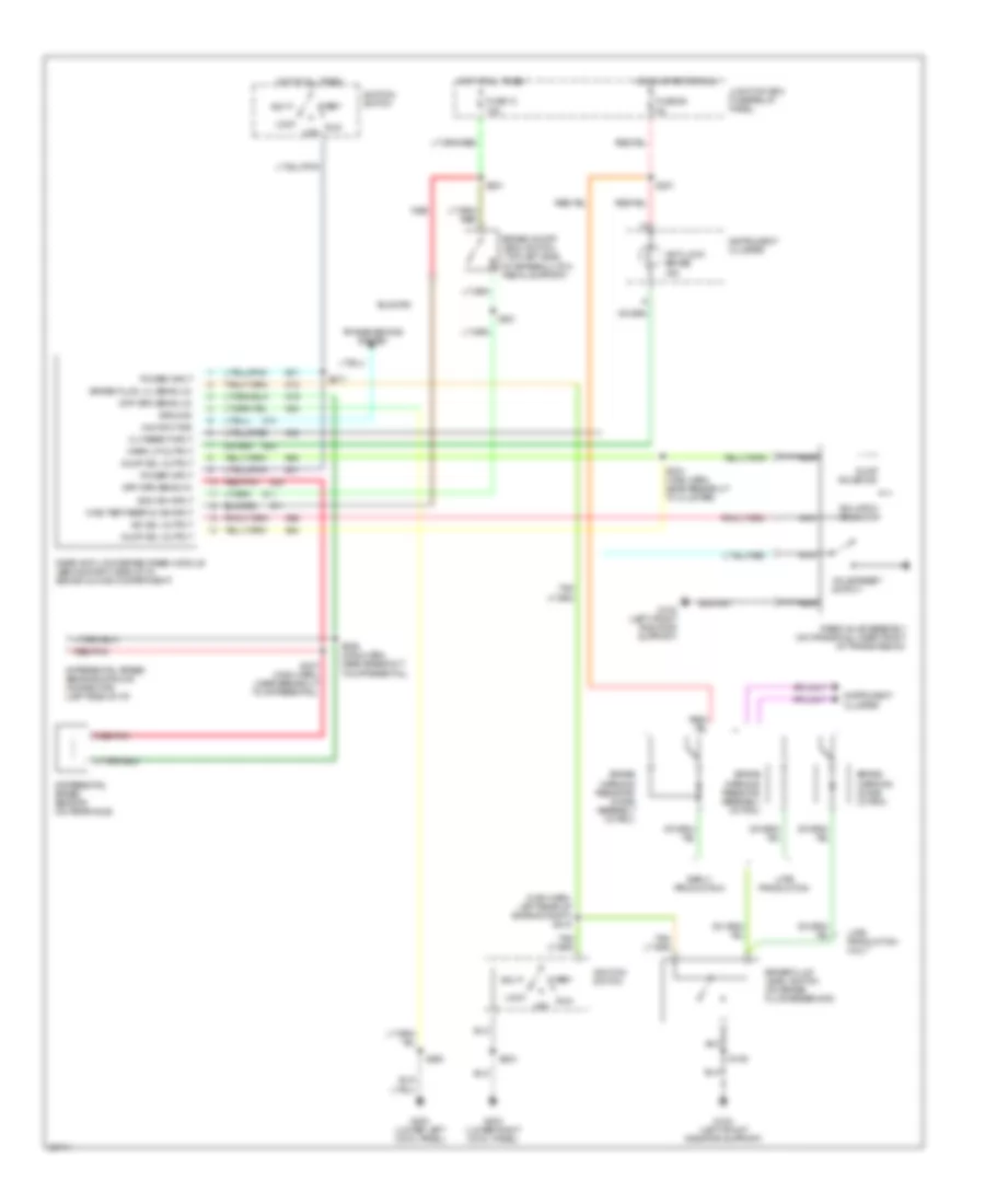
All-Wheel ABS Wiring Diagram for Ford Pickup F250 1997

List of elements for All-Wheel ABS Wiring Diagram for Ford Pickup F250 1997:
Rear Wheel ABS Wiring Diagram for Ford Pickup F250 1997
List of elements for Rear Wheel ABS Wiring Diagram for Ford Pickup F250 1997: