CRUISE CONTROL
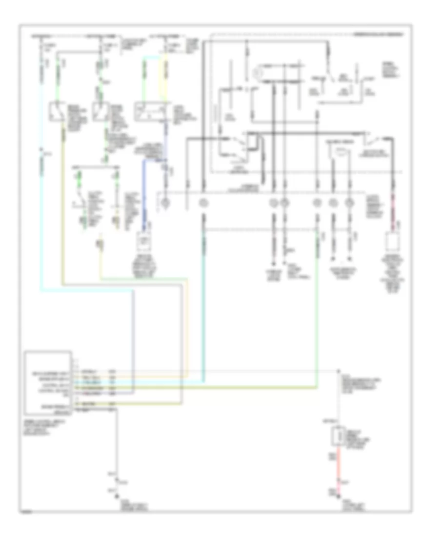
Cruise Control Wiring Diagram for Ford Pickup F250 1997
List of elements for Cruise Control Wiring Diagram for Ford Pickup F250 1997:
- (main harn, near breakout to clockspring assembly) s230
- (main harn, near breakout to instrument cluster) s231
- 15a
- 20a
- A/t
- Accel
- Brake on/off (boo) switch (behind left side of i/p)
- Brake press in
- Brake pressure switch (left rear corner of engine compt)
- C233
- C234
- C239
- C242
- C257
- Clock- spring assembly (top of steering column)
- Clutch pedal position (ccp) switch (on clutch pedal arm)
- Clutch pedal position (ccp) switch jumper (left side of i/p)
- Coast
- Control sw gnd
- Control sw in
- Driver's airbag
- Fuse 13
- Fuse 5
- G105 (rear of right fender apron)
- G200 (lower left cowl panel)
- G203 (lower right cowl panel)
- Generic electronic module (gem)/ central timer module (ctm) (behind center of i/p)
- Ground
- Horn relay (in power distribution box)
- Horn switches
- Hot at all times
- Hot in run
- Hrn rly
- Ign
- Ignition key warning switch
- Interior lights system
- Junction box fuse/relay panel
- M/t
- Nca
- Off
- Ohms
- Power distri- bution box
- Remote anti-theft personality (rap) module (behind left side of i/p)
- Resume
- S102
- S107
- S112
- S143 (engine sensor harn, near breakout to vapor management valve)
- S221
- Set/
- Speed control servo/ amplifier assembly (left side of engine compt)
- Speed control switch assembly
- Steering column assembly
- Steering column ground
- Vehicle speed input
- Vehicle speed sensor (vss) (left rear of trans)
 English