ANTI-LOCK BRAKES
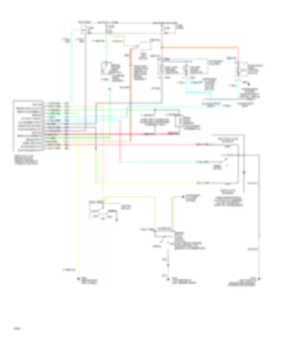
Anti-lock Brake Wiring Diagrams for Ford Ranger 1994
List of elements for Anti-lock Brake Wiring Diagrams for Ford Ranger 1994:
- engine compartment on radiator support)
- (left front of
- (on brake pedal support)
- (top center of
- (top of rear differential)
- 4x4
- 4x4 high range indicator
- 4x4 input signal
- Acc
- Anti-lock brakes indicator
- Brake fluid level switch (left rear of engine compartment, on brake fluid reservoir)
- Brake input
- Brake level fluid in
- Brake on/off (boo) switch
- C250
- Dump solenoid out
- Dump valve solenoid
- Electronic shift control switch
- Fuse 15a
- Fuse 20a
- Fuse panel
- G104
- G108
- G203 (behind right cowl panel)
- Ground
- Hot at all times
- Hot in run
- Hot in run or start
- Ignition
- Ignition switch
- Indicator control
- Instrument cluster
- Instrument cluster system
- Instrument cluster system (4x4 ind. switch)
- Iso solenoid out
- Isolation valve solenoid
- Left fender apron)
- Lock
- Low
- Main light switch
- Normal
- Off
- Rabs proportioning valve switch assembly (on left frame rail front of transmission)
- Rabs test connector (behind i/p, near park brake assembly)
- Rabs test connector (on engine compartment fuse/relay box)
- Rabs test/kam
- Rear anti-lock brake module (behind center of i/p below ashtray)
- Rear axle sensor
- Rear axle speed in
- Red
- Red/pnk
- Reset switch
- Run
- Start
- Transmission system (electric shift control module pin 5)
- Valve reset input
- W/electronic shift
- W/o electronic shift
 English