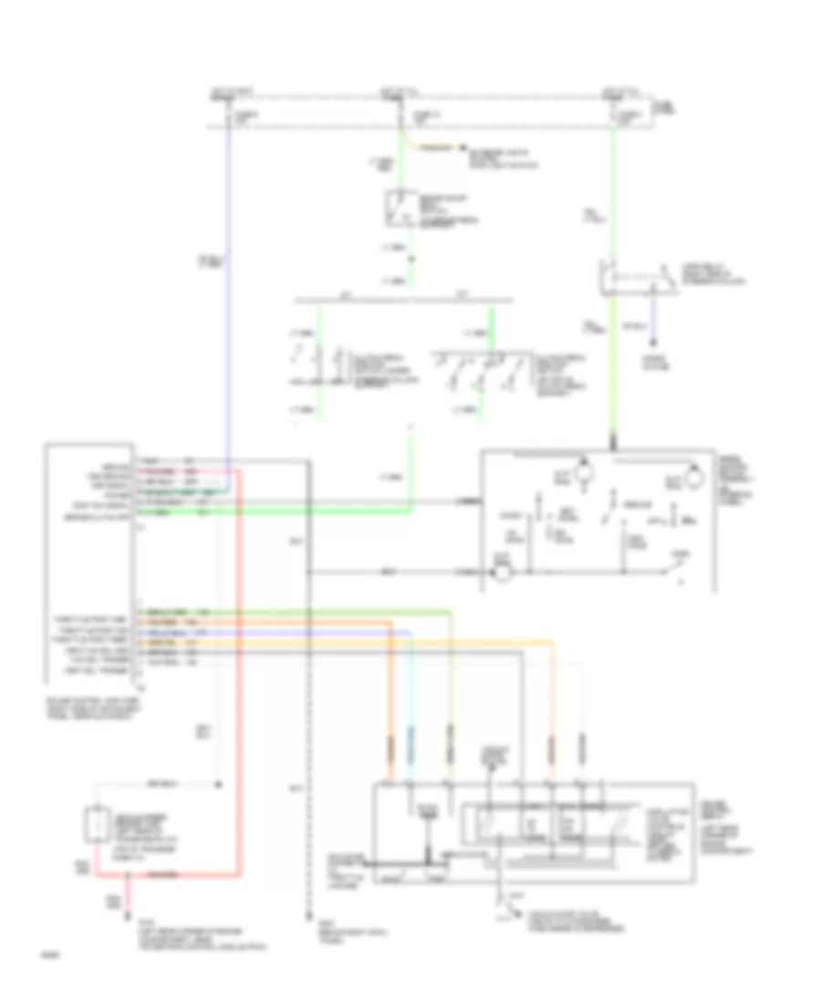
CRUISE CONTROL
Cruise Control Wiring Diagram for Ford Ranger 1994
List of elements for Cruise Control Wiring Diagram for Ford Ranger 1994:
- (behind right cowl
- (left rear corner of engine compartment)
- (left rear corner of engine
- (on brake pedal support)
- (on steering wheel)
- (on top of clutch pedal support)
- (top of transfer
- 100-
- 40-
- 50,000 ohms
- A/t
- Accel
- Actuator (connects to throttle linkage)
- Brake on/off (boo) switch
- Brake/clutch off
- Case 4*4)
- Clutch pedal position switch
- Clutch pedal position switch jumper
- Coast
- Compartment, near powertrain control module (pcm))
- Cont sw signal
- Cruise control amplifier (right side of instrument panel, near glove box)
- Cruise control servo
- Exterior lights system (main light switch)
- Fast
- Fuse 10 15a
- Fuse 6 10a
- Fuse 8 20a
- Fuse panel
- G104
- G203
- Ground
- Horn
- Horn relay (right side of steering column)
- Horns
- Hot at all times
- Hot in accy or run
- M/t
- Nca
- Off
- Ohms
- Panel)
- Power
- Resume
- Servo motor
- Set/
- Slip ring
- Slow
- Sol+
- Speed control switch assembly
- Steering column) support)
- System
- Throttle posit feed
- Throttle posit gnd
- Throttle posit sig
- Vac
- Vac sol trigger
- Vacuum distri- bution
- Vacuum dump valve (vents to atmosphere when brake is depressed)
- Vehicle speed sensor (vss) (left rear of transmission 4*2)
- Vent
- Vent sol trigger
- Vent/vac sol gnd
- Vss ground
- Vss signal
 English