ANTI-LOCK BRAKES
Anti-lock Brake Wiring Diagrams for Ford Windstar GL 1995
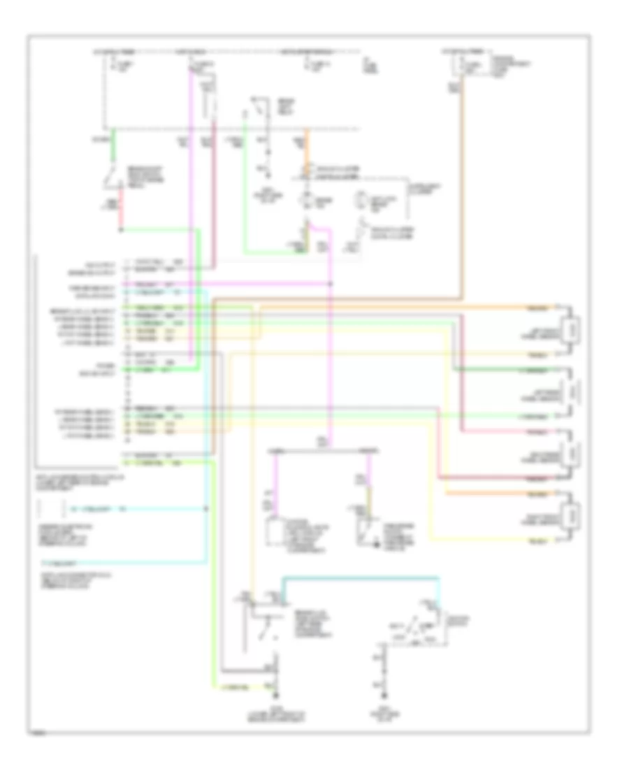
List of elements for Anti-lock Brake Wiring Diagrams for Ford Windstar GL 1995:
- Acc
- Analog cluster
- Anti-lock brake control module (lower left rear of engine compartment)
- Anti-lock brake ind
- Boo sw input
- Brake fluid level switch (left rear of engine compartment)
- Brake fluid lvl sw input
- Brake ind
- Brake ind output
- Brake lamp relay
- Brake on/off (boo) switch (top of brake pedal)
- Data link conn
- Data link connector (dlc) (below i/p, right of steering column)
- Daytime running lights (drl) module (left front of engine compartment)
- Digital cluster
- Engine compartment fuse box
- Fuse 14 15a
- Fuse 33 15a
- Fuse 7 15a
- Fuse l 60a
- G106 (lower left front of engine compartment)
- G201 (right side of i/p)
- Generic electronic module (gem) (behind i/p, left of steering column)
- Hot at all times
- Hot in run
- Hot in start or run
- I/p fuse panel
- Ignition switch
- Ind output
- Instrument cluster
- L fnt wheel sens (+)
- L fnt wheel sens (-)
- L rear wheel sens (+)
- L rear wheel sens (-)
- Left front wheel sensor
- Left rear wheel sensor
- Lock
- Off
- Park brake input
- Park brake switch (at base of park brake handle)
- Power
- Right front wheel sensor
- Right rear wheel sensor
- Rt fnt wheel sens (+)
- Rt fnt wheel sens (-)
- Rt rear wheel sens (+)
- Rt rear wheel sens (-)
- Run
- Start
- W/ drl
- W/o drl
 English