CRUISE CONTROL
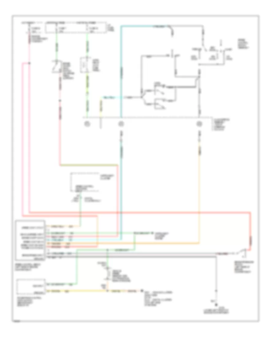
Cruise Control Wiring Diagram for Ford Windstar GL 1995
List of elements for Cruise Control Wiring Diagram for Ford Windstar GL 1995:
- (analog cluster)
- (digital cluster)
- (lower left front of engine compartment)
- 10a
- 15a
- Accel
- Brake on/off (boo) switch (on brake pedal support)
- Brake on/off sw in
- Brake press input
- Brake pressure switch (left rear of engine compartment)
- Clockspring assembly (top of steering column)
- Coast
- Digital cluster only
- Engine compartment fuse box
- Fuse 16
- Fuse 30
- Fuse 7
- G106
- G201 (right side of i/p) g134 (top left side of engine)
- Ground
- Horn relay (in i/p fuse panel)
- Horn switches
- Hot at all times
- Hot in run
- I/p fuse panel
- Instrument cluster
- Instrument cluster system
- Nca
- Off
- Ohms
- Power (hot in run)
- Powertrain control module (pcm) (behind right side of i/p)
- Resume
- Set/
- Speed cont lp out
- Speed cont sw gnd
- Speed cont sw in
- Speed control indicator input
- Speed control servo (left side of engine compartment)
- Speed control switch assembly
- Vehicle speed input
- Vehicle speed sensor (vss) (on transaxle, rear of engine)
- Vss input
 English