ANTI-LOCK BRAKES
Anti-lock Brakes Wiring Diagram for Hummer H2 2003
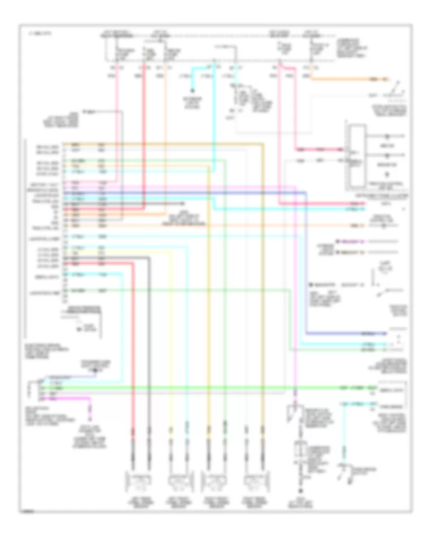
List of elements for Anti-lock Brakes Wiring Diagram for Hummer H2 2003:
- Abs fuse 60a
- Abs ind
- B12
- Body control module (bcm) (on top left side of dash, above i/p fuse block)
- Brake fld level
- Brake fluid level switch (on left side of brake fluid reservoir)
- Brake ind
- Brake pressure modulator valve
- C 1995 vftc
- C1 e7
- C2 b7
- Data link connector (dlc) (under left side of dash, below steering column)
- E11
- Electronic brake control module (ebcm) (left side of inner frame)
- Etc/ecm fuse 15a
- Exterior lights system
- F12
- G104 (at top left rear of eng)
- G200 (on left side of dash, near left kick panel)
- G300 (on left side of body mount, in front of driver door)
- G308 (at right frame body mount, near right rear door)
- Gnd
- Hot at all times
- Hot ignition 1 relay enerziged
- Hot in run or start
- I/p fuse block (on lower left side of dash)
- Ign 1
- Ign e fuse 10a
- Ignition 1 volt
- Illum
- Instrument panel cluster
- Interior lights system
- Left front wheel speed sensor
- Left rear wheel speed sensor
- Lf whl spd
- Lng rate 5v ref
- Lng rate lo ref
- Lng rate sig
- Longitudinal accelerometer (in center console, below radio)
- Lr whl spd
- Nca
- Park brake
- Park brake switch
- Pnk
- Pump motor
- Red
- Rf whl spd
- Right front wheel speed sensor
- Right rear wheel speed sensor
- Rr whl spd
- S102
- S217
- Seo b2 fuse 30a
- Serial data
- Splice pack sp205 (on left side of dash, near footwell courtesy lamp, on i/p harn)
- Stop lp fuse 25a
- Stop lp sw
- Stoplamp switch (on top of brake pedal bracket)
- Tan
- Trac ctrl ind
- Trac ctrl sig
- Traction control ind
- Traction control off ind
- Traction control switch
- Transfer case shift control module
- Underhood fuse block (at left side of eng compt, near battery)
- Veh stop fuse 15a
 English