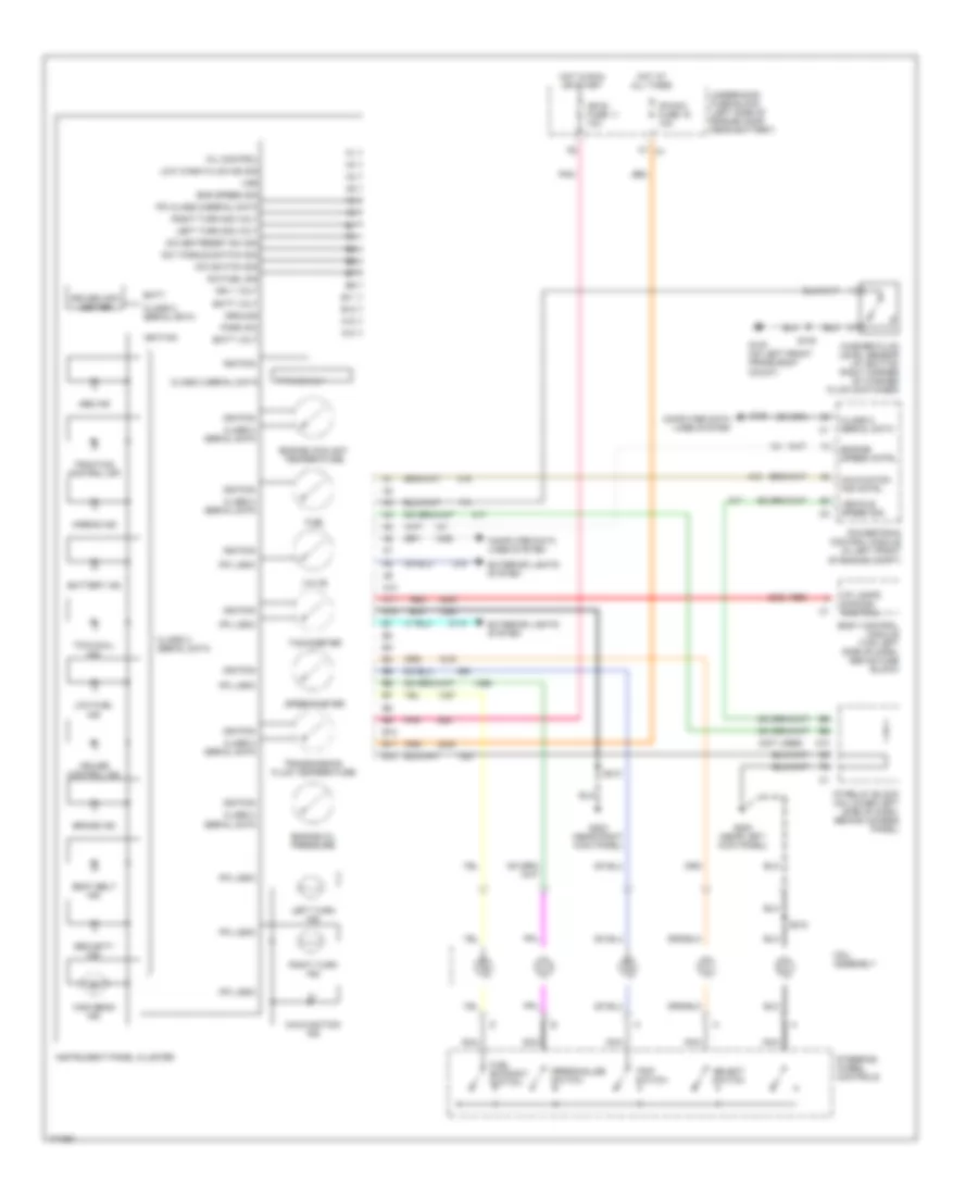
INSTRUMENT CLUSTER
Instrument Cluster Wiring Diagram for Hummer H2 2003
List of elements for Instrument Cluster Wiring Diagram for Hummer H2 2003:
- (not used)
- A10
- A11
- A12
- Abs ind
- Airbag ind
- B10
- B11
- B12
- Batt
- Batt volt
- Battery ind
- Body control module (top left side of dash, above fuse block)
- Brake ind
- Class 2 serial data
- Coil assembly
- Computer data lines system
- Cruise control ind
- Dic fuel sig
- Dic set/reset sw sig
- Dic switch sig
- Dic toggle switch sig
- Driver info center
- Eng speed sig
- Engine coolant temperature
- Engine oil pressure
- Engine speed cntrl
- Exterior lights system
- F7 c1
- Fuel
- Fuel economy switch
- G100 (on left front frame body mount)
- G200 (near left kick panel)
- G203 (near right kick panel)
- Ground
- High beam ind
- Hot at all times
- Hot in run or start
- I/p lamps dimming control
- I/p relay block (on lower left side of dash, behind access panel)
- Ign 1 volt
- Ign e fuse 11 10a
- Ignition
- Instrument panel cluster
- Ipc class 2/serial data
- Ipc logic
- Ipc/dic fuse 19 10a
- Left turn ind
- Left turn sig volt
- Low fuel ind
- Low wash fluid ind sig
- Malfunction ind
- Malfuntion ind cntrl
- Mil control
- Nca
- P r n d 3 2 1
- Park sw
- Personalize switch
- Pnk
- Powertrain control module (in left front of engine compt)
- Red
- Right turn ind
- Right turn sig volt
- S100
- S213
- S218
- Seat belt ind
- Security ind
- Select switch
- Speedometer
- Steering wheel controls
- Tachometer
- Tow/haul ind
- Traction control off
- Transmission fluid temperature
- Trip switch
- Underhood fuse block (left side of engine comp, near battery)
- Vehicle speed sig
- Volts
- Vss
- Washer fluid level sensor (at bottom right corner of washer fluid container)
 English