ANTI-LOCK BRAKES
Anti-lock Brakes Wiring Diagram for Mazda B4000 Dual Sport 2003
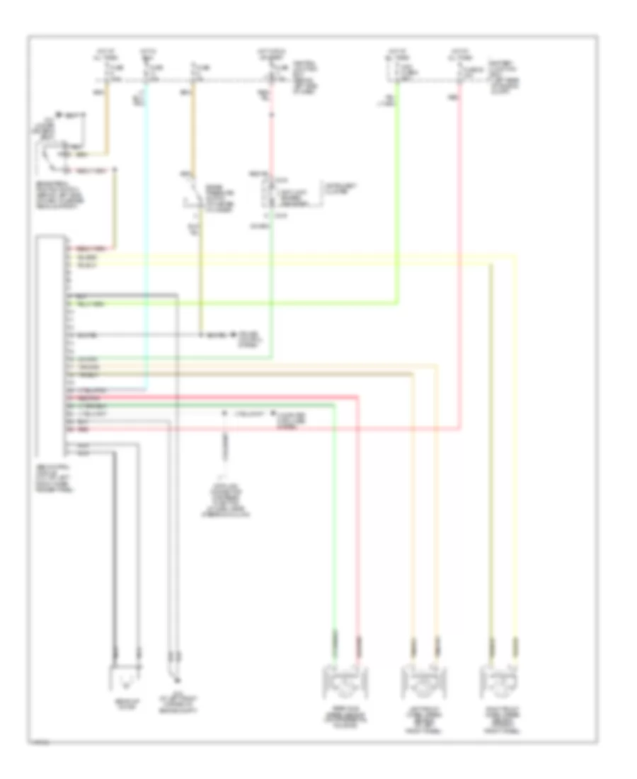
List of elements for Anti-lock Brakes Wiring Diagram for Mazda B4000 Dual Sport 2003:
- Abs control module (4.0l: on left front inner fender panel)
- Abs pump motor
- Anti-lock brakes indicator
- Battery junction box (left rear of engine compt)
- Brake pedal position switch (behind left side of dash, on brake pedal support)
- Brake pressure switch (at master cylinder)
- C215
- C216
- Central junction box (behind left side of dash)
- Computer data lines system
- Cruise control system
- Data link connector (fastened to bottom of dash, near steering column)
- Fuse 10a
- Fuse 28 30a
- Fuse 2a
- Fuse 7.5a
- G10 (under driver's seat)
- G12 (at left front corner of engine compt)
- Hot at all times
- Hot in run
- Hot in run or start
- Instrument cluster
- Left front wheel speed sensor (at left front wheel)
- Maxi fuse 6 50a
- Nca
- Rear axle speed sensor (on differential housing)
- Red
- Red/pnk
- Right front wheel speed sensor (at right front wheel)
 English