HORN
Horn Wiring Diagram, with Power Equipment for Mazda B4000 Dual Sport 2003

List of elements for Horn Wiring Diagram, with Power Equipment for Mazda B4000 Dual Sport 2003:
- 15a
- 20a
- 7.5a
- Air bag sliding contact
- Battery junction box (left rear of engine compt)
- Central junction box (behind left side of dash)
- Central security module (behind right kick panel)
- Cruise control system
- Driver's seat)
- Fuse 11
- Fuse 33
- Fuse 8
- G10 (under
- G3 (2.3l w/abs) g5 (others) (g3-left front corner of engine compt, g5-right rear corner if engine compt)
- G8 (under center of dash)
- Horn
- Horn switch
- Hot at all times
- Hot in run or start
- Nca
- Steering wheel
- T-409
- T-410
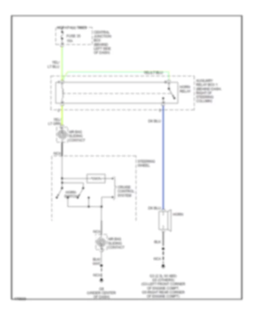
Horn Wiring Diagram, without Power Equipment for Mazda B4000 Dual Sport 2003
List of elements for Horn Wiring Diagram, without Power Equipment for Mazda B4000 Dual Sport 2003:
- 15a
- Air bag sliding contact
- Auxiliary relay box 1 (behind dash, right of steering column)
- Central junction box (behind left side of dash)
- Cruise control system
- Fuse 35
- G3 (2.3l w/ abs) g5 (others) (g3-left front corner of engine compt, g5-right rear corner of engine compt)
- G8 (under center of dash)
- Horn
- Horn relay
- Horn switch
- Hot at all times
- Nca
- Steering wheel