ANTI-LOCK BRAKES
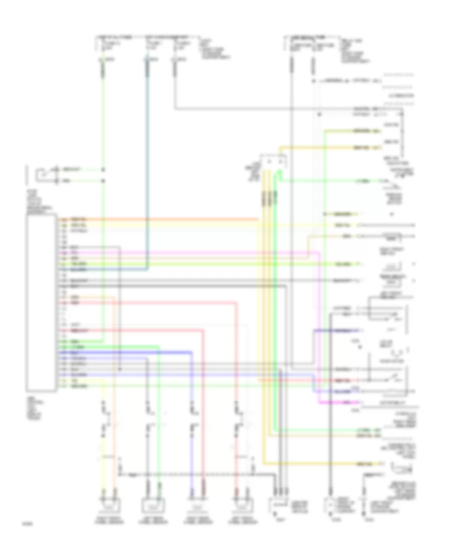
Anti-lock Brake Wiring Diagrams for Mazda RX-7 1994
List of elements for Anti-lock Brake Wiring Diagrams for Mazda RX-7 1994:
- (canada only) drl control unit (left kick panel)
- (center rear of vehicle)
- (left front of engine compartment)
- (right front of engine compart)
- (right side of engine compartment)
- (top of brake pedal support)
- 1d
- Abs control unit (left side of trunk)
- Abs fuse 15a
- Abs fuse 60a
- Abs ind
- Alternator
- Brake fluid level switch (left rear of engine compartment)
- Brk ind
- Chg ind
- Fuse 1 10a
- Fuse 10 20a
- Fuse 9 15a
- G108
- G109
- G407
- Hot at all times
- Hot in run and start
- Hydraulic unit (right rear eng comp)
- Indicators
- Instrument cluster
- Joint box
- Left front abs sol
- Left front wheel sensor
- Left rear wheel sensor
- Motor relay
- O-02
- O-03
- Parking brake switch
- Pump motor
- Rear abs sol
- Red
- Relay and fuse box
- Right front abs sol
- Right front wheel sensor
- Right rear wheel sensor
- Stop lamp switch
- Valve relay
- X-06 (behind left side of i/p)
 English