AIR CONDITIONING
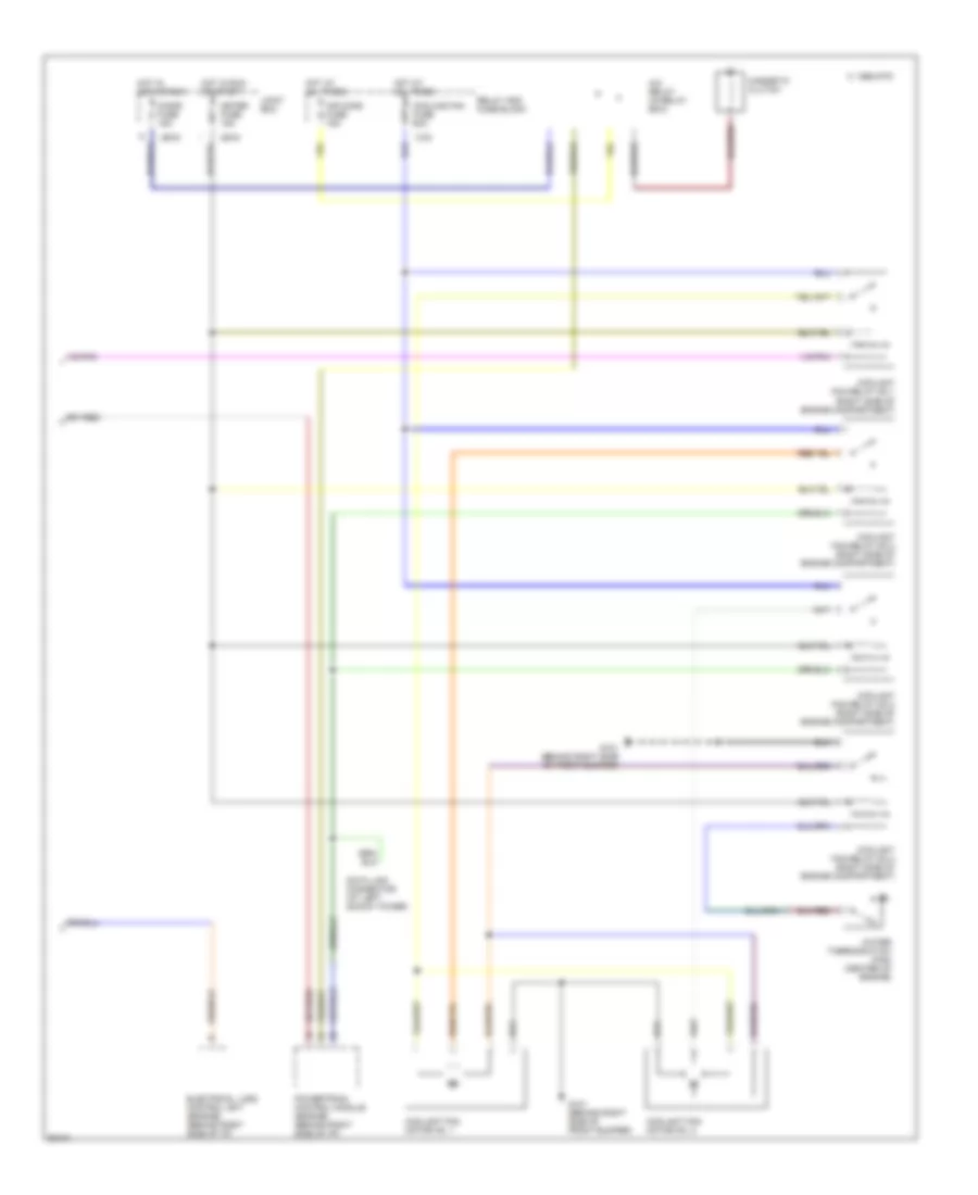
A/C Wiring Diagram (1 of 2) for Mazda RX-7 1994

List of elements for A/C Wiring Diagram (1 of 2) for Mazda RX-7 1994:
- (amplifier)
- (behind center
- (behind center of i/p)
- (left kick panel)
- (right kick panel)
- Air conditioning sensor
- Air intake actuator (behind right of i/p)
- Air mix actuator (behind center of i/p)
- Airflow mode actuator (behind center of i/p)
- B/l
- B2 fuse 40a
- Blower motor
- Blower relay (behind right side of i/p)
- C 1995 vftc
- Cold
- Com
- Def
- G200 or g203
- G206
- G206 (behind center of i/p)
- H/d
- Heat
- Heater control unit
- Heater control unit (controller)
- Heater control unit (fan switch)
- Hot
- Hot at all times
- Hot in run or start
- Jb-02
- Jb-07
- Joint box
- Main fuse box
- Nca
- Of i/p)
- Off
- Rear wiper fuse 10a
- Red
- Refrigerant pressure switch (left front of engine compartment)
- Resistor (behind right side of i/p)
- Thermoswitch (behind right side of i/p)
- Transmission controls system
- Vent
- X-08
A/C Wiring Diagram (2 of 2) for Mazda RX-7 1994
List of elements for A/C Wiring Diagram (2 of 2) for Mazda RX-7 1994:
- A/c relay (in relay box)
- Air cond fuse 15a
- C 1995 vftc
- Cigar fuse 15a
- Coolant fan motor no. 1
- Coolant fan motor no. 2
- Coolant fan relay no.1 (right side of engine compartment)
- Coolant fan relay no.2 (right side of engine compartment)
- Coolant fan relay no.3 (right side of engine compartment)
- Coolant fan relay no.4 (right side of engine compartment)
- Cooling fan fuse 60a
- Data link connector (at left shock tower)
- Electrical load control unit (engine) (behind right side of i/p)
- G101 (behind right side of front bumper)
- Hot at all times
- Hot in acc or run
- Hot in run or start
- Jb-03
- Jb-04
- Joint box
- Magnetic clutch
- Meter fuse 15a
- Powertrain control module (engine) (behind right side of i/p)
- Relay and fuse block
- Water thermoswitch (fan) (center of engine)
- X-02