ANTI-LOCK BRAKES
Anti-lock Brakes Wiring Diagram, Basic (1 of 2) for Mercedes-Benz CLS550 2012

List of elements for Anti-lock Brakes Wiring Diagram, Basic (1 of 2) for Mercedes-Benz CLS550 2012:
- (-)
- (left side of engine compt) electronic stability program (esp) control unit
- + 12v
- 30g
- Bla
- Bls h
- Bls l
- Bls m
- Brake vacuum sensor (w/ eco start/stop function) (attached to brake booster)
- Can e h
- Can e l
- Can h h
- Can h l
- Computer data lines system
- Df hl m
- Df hl s
- Df hr m
- Df hr s
- Df vl m
- Df vl s
- Df vr m
- Df vr s
- Eco
- Eco 12v
- Front axle brake pressure sensor
- Front axle intake ball valve
- Front axle switch over valve
- High pressure & return pump
- K-line
- Left front axle rpm sensor (at left front wheel assembly)
- Left front pressure regulator valve (pressure hold)
- Left front pressure regulator valve (pressure release)
- Left rear axle rpm sensor (at left rear wheel assembly)
- Left rear pressure regulator valve (pressure hold)
- Left rear pressure regulator valve (pressure release)
- Nca
- Pml
- Pml 12v
- Power steering pump quantity control valve
- Rear axle intake ball valve
- Rear axle switch over valve
- Rear sam control unit w/ fuse & relay module (right side c9i of trunk)
- Right front axle rpm sensor (at right front wheel assembly)
- Right front pressure regulator valve (pressure hold)
- Right front pressure regulator valve (pressure release)
- Right rear axle rpm sensor (at right rear wheel assembly)
- Right rear pressure regulator valve (pressure hold)
- Right rear pressure regulator valve (pressure release)
- Sig
- Ssk stat
- Stop lamp switch (under left side of dash)
- Traction system hydraulic unit (left front engine compt)
- W70 (lower left front of engine compt)
- X26-c1
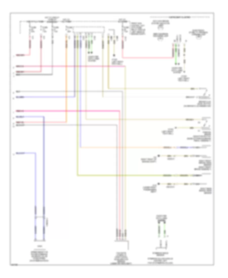
Anti-lock Brakes Wiring Diagram, Basic (2 of 2) for Mercedes-Benz CLS550 2012
List of elements for Anti-lock Brakes Wiring Diagram, Basic (2 of 2) for Mercedes-Benz CLS550 2012:
- Antilock brake system indicator lamp
- Brake fluid level switch (on brake fluid reservoir)
- C11c
- C15m
- C19i
- C20m
- C22i
- C2i
- C7i
- Can b h
- Can b l
- Can e h
- Can e l
- Computer data lines system
- Electronic stability program warning lamp
- Front sam control unit with fuse/ relay module (left rear of engine compt)
- Fuse 25a
- Fuse 40a
- Fuse 7.5a
- Hot at all times
- Hot w/ circuit 15 relay energized
- Instrument cluster
- Nca
- Parking brake indicator switch (base of parking brake pedal assembly)
- Right front brake wear sensor (right front brake assembly)
- Right rear brake wear sensor
- Service brake indicator lamp
- Speed-sensitive power steering solenoid valve (if equipped) (on steering rack)
- Steering angle sensor
- Steering column module control unit (top of steering column)
- W15/2 (left front footwell)
- W15/5 (left front footwell)
- W19 (under front passenger's seat)
- W2 (right front of engine compt)
- X18/33-c1
- X62/33-c1
- X62/6-c1
- Yaw rate, lateral & longitudinal acceleration sensor (under driver's seat)
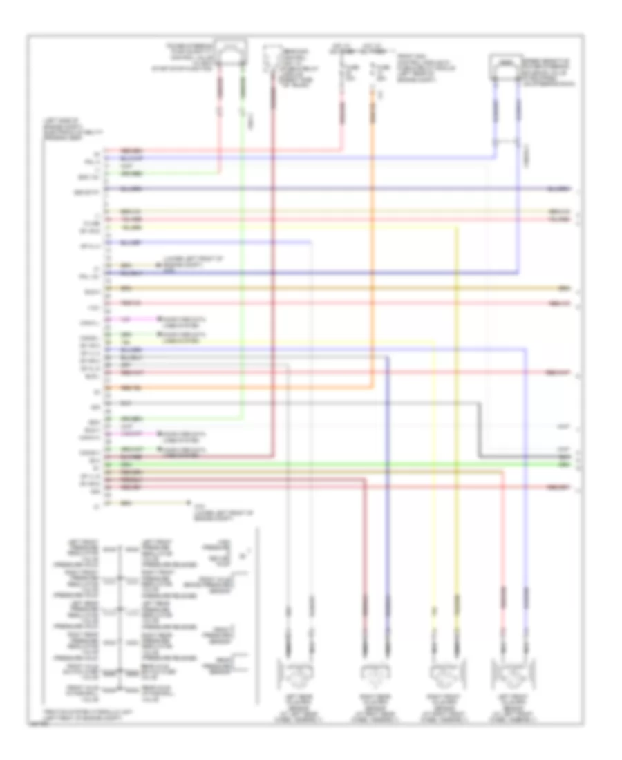
Anti-lock Brakes Wiring Diagram, Premium (1 of 2) for Mercedes-Benz CLS550 2012
List of elements for Anti-lock Brakes Wiring Diagram, Premium (1 of 2) for Mercedes-Benz CLS550 2012:
- (-)
- (left side of engine compt) electronic stability program (esp)
- (lower left front of engine compt) w70
- +12v
- 30g
- Bla
- Bls h
- Bls m
- Bls-l
- C7i
- Can-e h
- Can-e l
- Can-h h
- Can-h l
- Computer data lines system
- Df hl m
- Df hl s
- Df hr m
- Df hr s
- Df vl m
- Df vl s
- Df vr m
- Df vr s
- Eco
- Eco 12v
- Front axle brake pressure sensor
- Front axle intake ball valve
- Front axle switch over valve
- Front pressure sensor
- Front sam control module w/ fuse & relay module (left rear of engine compt)
- Fuse 25a
- Fuse 40a
- High pressure & return pump
- Hot at all times
- K-line
- Left front axle rpm sensor (at left front wheel assembly)
- Left front pressure regulator valve (pressure hold)
- Left front pressure regulator valve (pressure release)
- Left rear axle rpm sensor (at left rear wheel assembly)
- Left rear pressure regulator valve (pressure hold)
- Left rear pressure regulator valve (pressure release)
- Nca
- Pml 12v
- Pml a
- Power steering pump quantity control valve (w/ eco start/stop function)
- Rear axle intake ball valve
- Rear axle switch over valve
- Rear pressure sensor
- Rear sam control unit w/ fuse & relay module c9i (right side of trunk)
- Right front axle rpm sensor (at right front wheel assembly)
- Right front pressure regulator valve (pressure hold)
- Right front pressure regulator valve (pressure release)
- Right rear axle rpm sensor (at right rear wheel assembly)
- Right rear pressure regulator valve (pressure hold)
- Right rear pressure regulator valve (pressure release)
- Sig
- Speed sensitive power steering solenoid valve (if equipped) (on steering rack)
- Ssk-stat
- Traction system hydraulic unit (left front of engine compt)
- W70 (lower left front of engine compt)
- X18/33-c1
- X26-c1
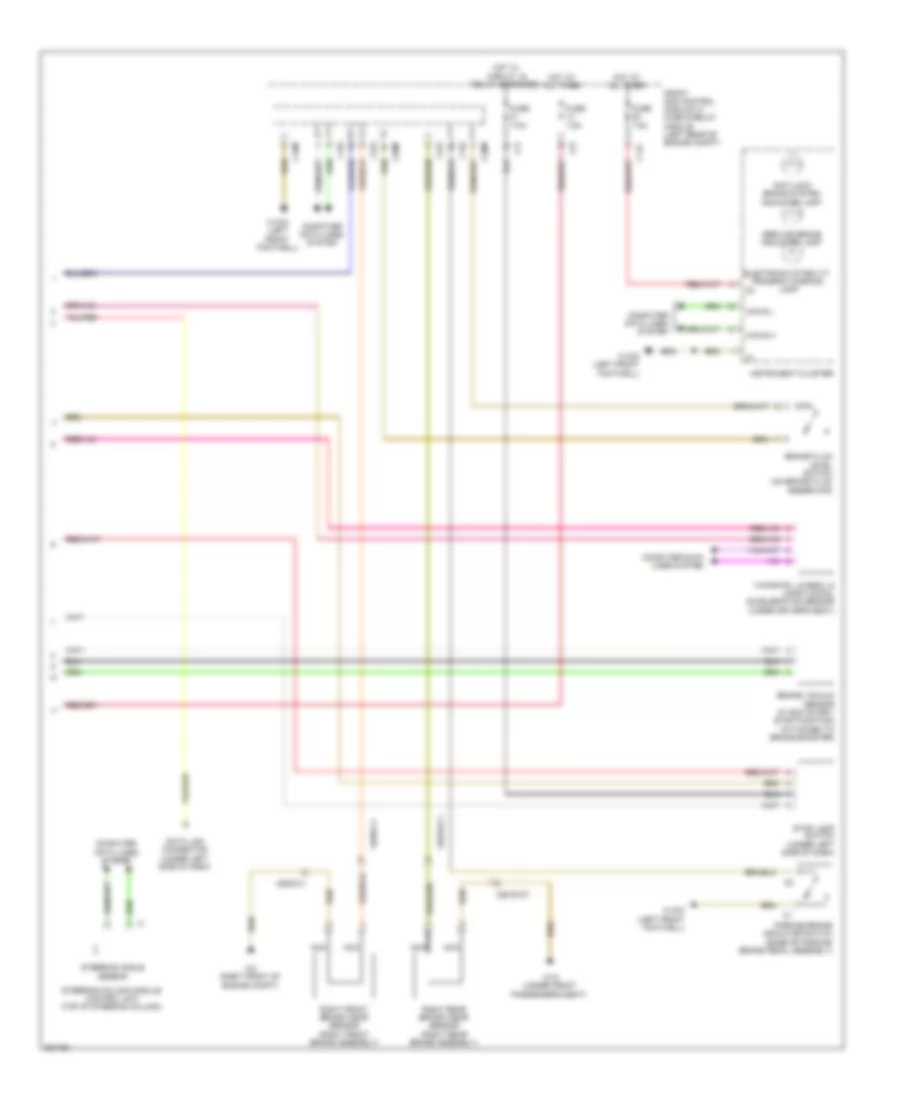
Anti-lock Brakes Wiring Diagram, Premium (2 of 2) for Mercedes-Benz CLS550 2012
List of elements for Anti-lock Brakes Wiring Diagram, Premium (2 of 2) for Mercedes-Benz CLS550 2012:
- Anti-lock brake system indicator lamp
- Brake fluid level switch (on brake fluid reservoir)
- Brake vacuum sensor (w/ eco start/ stop function) (attached to brake booster)
- C11c
- C15m
- C19i
- C20m
- C22i
- C2i
- C7i
- Can e h
- Can e l
- Computer data lines system
- Data link connector (under left side of dash)
- Electronic stability program warning lamp
- Front sam control module w/ fuse & relay module (left rear of engine compt)
- Fuse 7.5a
- Hot at all times
- Hot w/ circuit 15 relay energized
- Instrument cluster
- Nca
- Parking brake indicator switch (base of parking brake pedal assembly)
- Right front brake wear sensor (right front brake assembly)
- Right rear brake wear sensor (right rear brake assembly)
- Service brake indicator lamp
- Steering angle sensor
- Steering column module control unit (top of steering column)
- Stop lamp switch (under left side of dash)
- W15/2 (left front footwell)
- W15/5 (left front footwell)
- W19 (under front passenger's seat)
- W2 (right front of engine compt)
- X62/33-c1
- X62/6-c1
- Yawrate, lateral & longitudinal acceleration sensor (under driver's seat)