ELECTRONIC POWER STEERING
Electronic Power Steering Wiring Diagram for Mercedes-Benz CLS550 2012

List of elements for Electronic Power Steering Wiring Diagram for Mercedes-Benz CLS550 2012:
- Can-e h
- Can-e l
- Computer data lines system
- Electric power steering actuator motor
- Electric power steering torque sensor (on steering rack assembly)
- Electrical power steering control unit (on steering rack)
- Front electrical prefuse box (right rear of engine compt)
- Fuse 80a
- Hot at all times
- Mr3
- Nca
- Red
- W2/1 (right front wheel well)
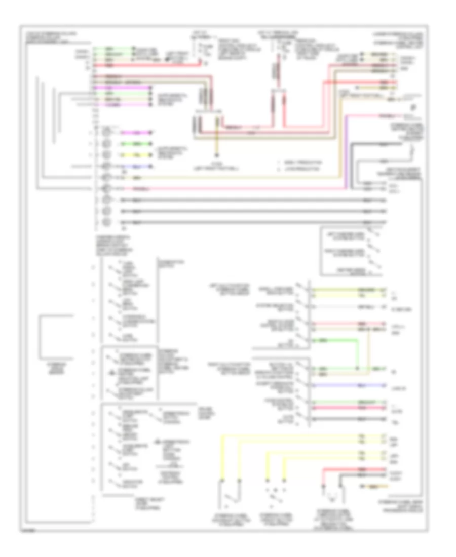
Power Steering Column Wiring Diagram for Mercedes-Benz CLS550 2012
List of elements for Power Steering Column Wiring Diagram for Mercedes-Benz CLS550 2012:
- (left front footwell)
- (left front footwell) w15/5
- (top of steering column) steering column module control unit
- (under steering column) (if equipped) steering wheel heater control unit
- +, -
- 12i
- Accelerate & set switch
- Accept/terminate phone call button
- Aldw+
- Aldw-
- Back & voice control system off button
- Button + & - setting of specific functions & volume control
- Can-b h
- Can-b l
- Can-e h
- Can-e l
- Center horns button
- Combination switch
- Computer data lines system
- Cruise control lever
- Decelerate & set switch
- Direct select lever (if equipped)
- Distronic control (if equipped)
- Early production
- Fanfare horns & air bag clock spring contact (part of steering column module)
- Front sam control module w/ fuse & relay module (left rear of engine compt)
- Fuse 7.5a
- Gnd
- Head lamp flasher/high beam switch
- Heating element temperature sensor (if equipped)
- Hot at all times
- Hot w/ terminal 30g relay energized
- Indicator switch
- Late production
- Left fanfare horn system button
- Left multi-function steering wheel button group
- Low beam switch
- Lsp+
- Lsp-
- Mute
- Mute button
- Nca
- Ntc +
- Ntc -
- Off switch
- Ok button
- Pnk
- R, return
- Rear sam control module w/ fuse & relay module (right side of trunk)
- Red
- Resume from memory switch
- Right fanfare horn system button
- Right multi-function steering wheel button group
- Scroll forward/ back button
- Speedtronic light emitting diode (canada)
- Speedtronic switch (canada)
- Steering angle sensor
- Steering column adjustment & steering wheel heater switch
- Steering column adjustment switch
- Steering wheel downshift button (if equipped)
- Steering wheel gear shift signal processing module
- Steering wheel heater heating element (if equipped)
- Steering wheel heater indicator lamp (if equipped)
- Steering wheel heater switch (if equipped)
- Steering wheel upshift button (if equipped)
- Steering wheel vibration motor (w/ automatic lane recognition) (in steering wheel)
- System selection button
- Tel
- Turn signal lamp switch
- U-mfl-r
- U-mll-l
- Voice control system on button
- W15/2 (left front footwell)
- W15/5
- Windshield washer system switch
- Wipe switch
- X18