ANTI-LOCK BRAKES
Anti-lock Brakes Wiring Diagram for Mitsubishi Galant SE 2010
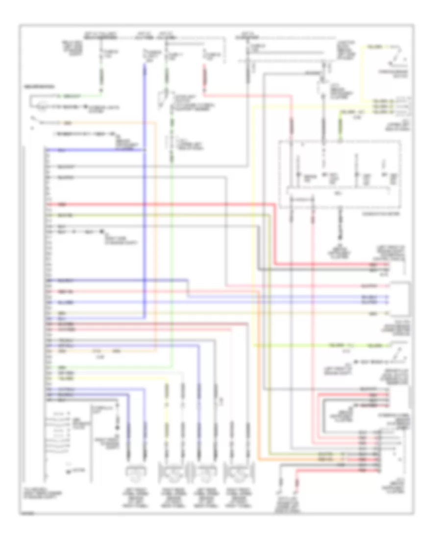
List of elements for Anti-lock Brakes Wiring Diagram for Mitsubishi Galant SE 2010:
- (left front of engine compt) powertrain control module
- A-13
- Abs solenoid valve
- Anti lock ind
- Asc off ind
- Asc off switch
- Asc/ tcl ind
- B-19
- Brake fluid level switch (in brake fluid reservoir)
- Brake ind
- C-211
- C-214
- C-25
- C-29
- Combination meter
- Cpu
- Data link connector (under left side of dash)
- Fuse 11 15a
- Fuse 20 7.5a
- Fuse 22 10a
- Fuse 23 7.5a
- Fusible link 3 60a
- G & yaw rate sensor (under center console)
- G1 (right side of engine compt)
- G11 (left front of engine compt)
- G6 (behind instrument cluster)
- G8 (right front of engine compt)
- Hot at all times
- Hot in on or start
- Hot w/ taillight relay energized
- Hydraulic unit
- Interior lights system
- J/c 1 (upper left end of dash)
- J/c 2 (behind instrument cluster)
- J/c 3 (behind instrument cluster)
- Junction block (behind left side of dash)
- Left front wheel speed sensor (at left front wheel)
- Left rear wheel speed sensor (at left rear wheel)
- Motor m
- Nca
- Parking brake switch
- Red
- Relay box (left side of engine compt)
- Right front wheel speed sensor (at right front wheel)
- Right rear wheel speed sensor (at right rear wheel)
- Steering wheel sensor (in steering wheel)
- Stoplight switch (attached to pedal support member)
- Tcl/asc-ecu (right rear corner of engine compt)
 English