ANTI-LOCK BRAKES
Anti-lock Brakes Wiring Diagram for Mitsubishi Mirage ES 2014
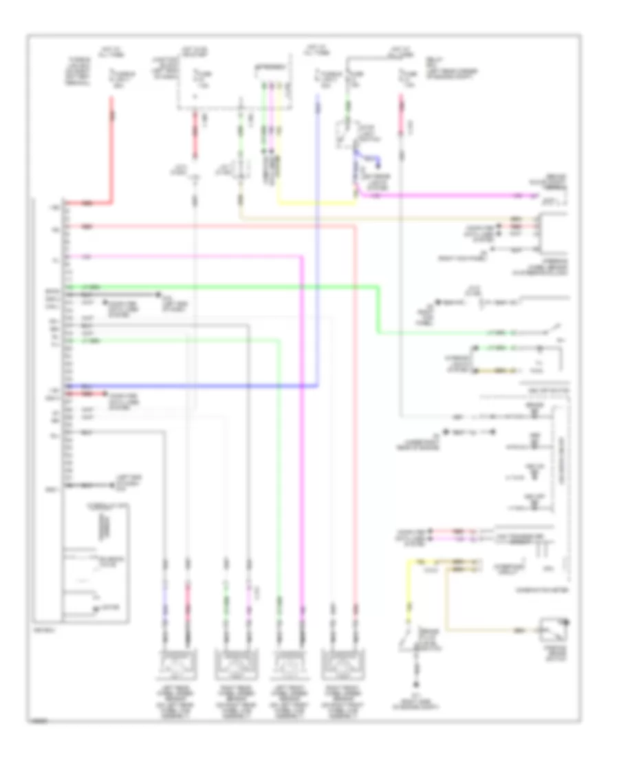
List of elements for Anti-lock Brakes Wiring Diagram for Mitsubishi Mirage ES 2014:
- (behind glove compt) oss-ecu
- (left end of dash) g19
- + bm
- + bv
- Abs ind
- Asc off ind
- Asc off switch
- Asc on ind
- Asc-ecu
- Brake fluid level switch
- Brake ind
- C-211
- C-212
- C-213
- C-404
- C-405
- C-416
- Can h
- Can l
- Can transceiver circuit
- Combination meter
- Computer data lines system
- Cpu
- Etacs-ecu
- Exterior lights system
- Fl+
- Fl-
- Fr +
- Fr-
- Fuse 15a
- Fuse 7.5a
- Fusible link 2 30a
- Fusible link 4 60a
- Fusible link box (on right battery terminal)
- G11 (right side of engine compt)
- G19 (left end of dash)
- G3 (right kick panel)
- G4 (under right rear of engine)
- Gnd 1
- Gnd 2
- Hot at all times
- Hot in on or start
- Hydraulic unit
- Ig1
- Ill
- Interface circuit
- Interior lights system
- J/c 2 (c-204)
- J/c 7 (c-105)
- J/c 9 (c-109)
- Junction block (left end of dash)
- Led drive circuit
- Left front wheel speed sensor (on left front wheel hub assembly)
- Left rear wheel speed sensor (on left rear wheel hub assembly)
- Motor m
- Nca
- Parking brake switch
- Pnk
- Red
- Relay box (left rear corner of engine compt)
- Right front wheel speed sensor (on right front wheel hub assembly)
- Right rear wheel speed sensor (on right rear wheel hub assembly)
- Rl+
- Rl-
- Rr+
- Rr-
- Sensor pressure
- Solenoid valve
- Steering wheel sensor (in steering column)
- Stop light switch
- Stp 1
- Swon
- System data lines computer
 English