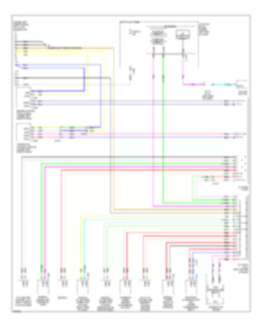
COMPUTER DATA LINES
Computer Data Lines Wiring Diagram for Mitsubishi Mirage ES 2014
List of elements for Computer Data Lines Wiring Diagram for Mitsubishi Mirage ES 2014:
- (under left side of dash) data link connector
- Asc-ecu
- Auto a/c controller assembly (a/c ecu) (center of dash)
- C-104
- C-117
- C-207
- C-209
- C-212
- C-213
- C-215
- C-227
- C-228
- C-29
- C-403
- C-416
- Can drive circuit
- Can h
- Can l
- Can transceiver circuit
- Can+
- Can-
- Canh
- Canl
- Circuit
- Cnbh
- Cnbl
- Column switch
- Combination meter
- Cpu
- D-37
- Data
- Diad
- Engine control module (ecm) (under left side of dash)
- Eps-ecu (under left center of dash)
- Etacs-ecu
- Fmb
- Fpcu
- Fuse 12 15a
- G4 (under right rear of engine)
- Hot at all times
- Interface circuit
- J/c (can1) (c-01) (left center of dash)
- J/c (can2) (c-203)
- J/c 10 (c-10) (left side of dash)
- Junction block (under left end of dash)
- Kos-ecu (w/ keyless operating system) (right side of dash)
- Lin
- Lin interface
- Occupant classification ecu (under passenger's seat)
- Oss-ecu (w/ keyless operating system) (behind glove compartment)
- Pnk
- Ptc heater control unit (right side of hvac blower)
- Red
- Srs-ecu (under front of center console)
- Steering wheel sensor (in steering column)
- Transaxle control module (under left side of dash)
 English