ANTI-LOCK BRAKES
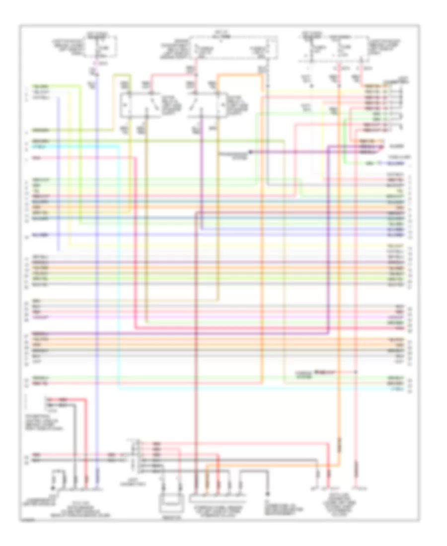
Anti-lock Brakes Wiring Diagram (1 of 3) for Mitsubishi Montero Limited 2006

List of elements for Anti-lock Brakes Wiring Diagram (1 of 3) for Mitsubishi Montero Limited 2006:
- (on transfer case)
- (on transfer case) center differential lock detection switch
- (under center of dash, near abs ecu) g11
- 2wd detection switch (rear of transmission)
- 2wd/4wd detection switch (on transfer case)
- 4h detection switch
- 4llc detection switch (rear of transmission)
- Active skid control switch
- E119
- E120
- E121
- Fuse 10a
- G11 (under center of dash, near abs ecu)
- G8 (under dash, on passenger side reinforcement)
- Hot in run
- Illum
- Interior lights system
- Junction block (behind lower left side of dash)
- Left front wheel speed sensor (attached to abs rotor protector)
- Left rear wheel speed sensor (attached to abs rotor protector)
- M-astc ecu (behind center of dash)
- Nca
- Off
- Pnk
- Red
- Right front wheel speed sensor (attached to abs rotor protector)
- Right rear wheel speed sensor (attached to abs rotor protector)
- Starting/charging system
- Trans- missions system
- Transfer ecu (behind center of dash)
- Transmissions system
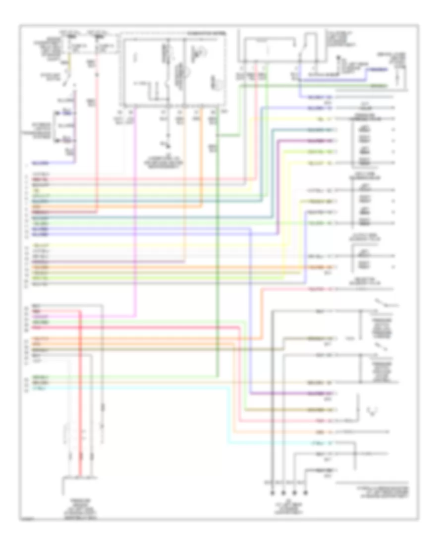
Anti-lock Brakes Wiring Diagram (2 of 3) for Mitsubishi Montero Limited 2006
List of elements for Anti-lock Brakes Wiring Diagram (2 of 3) for Mitsubishi Montero Limited 2006:
- "g" & yaw rate sensor (in center console, rear of parking brake lever)
- Buzzer
- D117
- D118
- D134
- D210
- D212
- Data link connector (lower left side of dash, right of steering column)
- Engine compartment relay box (left side of engine compt)
- Fuse 10a
- Fuse 6 10a
- Fusible link 31 60a
- Fusible link 32 40a
- G16 (under rear of center console)
- G7 (under dash, on driver side center reinforcement)
- Hot at all times
- Hot in run
- Hot in run or start
- Joint connector 4
- Joint connector 5
- Junction block (behind lower left side of dash)
- Motor relay a (left side of engine compt)
- Motor relay b (left side of engine compt)
- Nca
- Pnk
- Powertrain control module (behind lower right side of dash)
- Red
- Resistor
- Steering wheel sensor (on left side of upper steering column)
- Tone alarm
- Transmissions system
- Warning system
Anti-lock Brakes Wiring Diagram (3 of 3) for Mitsubishi Montero Limited 2006
List of elements for Anti-lock Brakes Wiring Diagram (3 of 3) for Mitsubishi Montero Limited 2006:
- (behind lower center of dash)
- (under dash, on driver side center reinforcement)
- Abs ind
- Ascs off ind
- Ascs/atcs operation ind
- B14
- B17
- B18
- Brake ind
- Combination meter
- Cut valve
- D03
- Diode
- Engine compartment relay box (left side of engine compt)
- Exterior lights & transmissions systems
- Fuse 16 15a
- Fuse 18 15a
- G3 (at left rear of engine compartment)
- G3 (at left rear of engine compt)
- Hot at all times
- Hydraulic brake booster (at left rear corner of engine compartment)
- Input side solenoid valve
- Left front
- Left rear
- Output side solenoid valve
- Pnk
- Pressure increase valve
- Pressure sensor (on left side of engine compt, near relay box)
- Pressure switch (for low- pressure warning)
- Pressure switch (for pump motor control)
- Red
- Right front
- Right rear
- Selection solenoid valve
- Stoplight switch
- Valve relay (left side of engine compartment)