INSTRUMENT CLUSTER
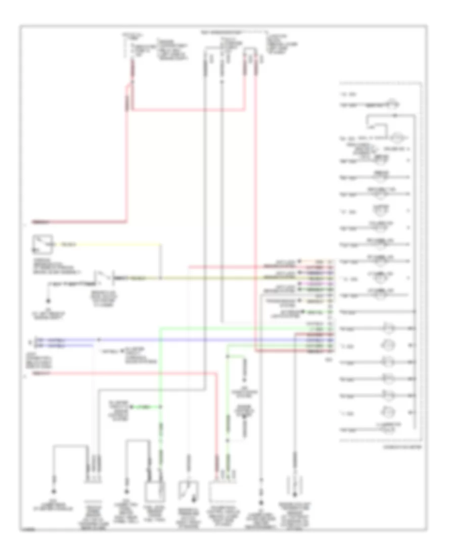
Instrument Cluster Wiring Diagram (1 of 2) for Mitsubishi Montero Limited 2006

List of elements for Instrument Cluster Wiring Diagram (1 of 2) for Mitsubishi Montero Limited 2006:
- A/t temp ind
- Asc off ind
- Back door ind
- Back door switch
- Brake ind
- Charge ind
- Check engine ind
- Clock
- Combination meter
- Cpu
- Cruise control system
- D03
- D03 52
- D04
- D04 38
- D32
- D32 16
- D32 17
- D32 18
- D32 19
- D32 20
- Dedicated fuse 17 10a
- Dedicated fuse 23 10a
- Door locks system
- Door locks, power windows, power tops & anti-theft systems
- Engine compartment relay box (left side of engine compt)
- Exterior lights system
- Fog ind
- Fuel gauge
- Fuel ind
- G7 (under dash, on driver side center reinforcement)
- Headlights system
- Hot in acc or run
- Hot w/ taillight relay energized
- Interior lights system
- Left front door ind
- Left front door switch
- Left rear door ind
- Left rear door switch
- Left turn ind
- Oil ind
- Pnk
- Red
- Right front door ind
- Right front door switch
- Right rear door ind
- Right rear door switch
- Right turn ind
- Speedometer
- Starting/ charging system
- Tachometer
- Tcs off ind
- Temperature gauge
- To abs ind (diagram 2 of 2)
- Tpms ind
- Transmissions system
- Warning system
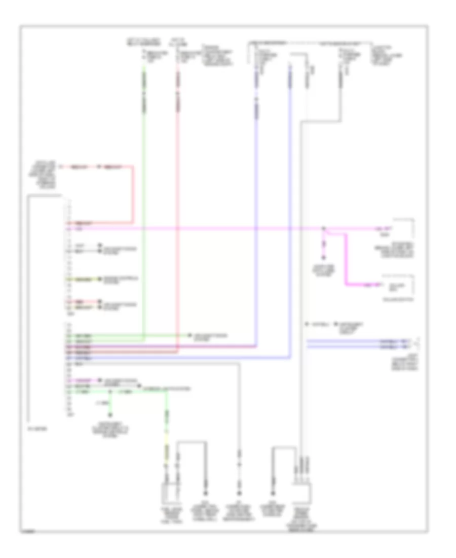
Instrument Cluster Wiring Diagram (2 of 2) for Mitsubishi Montero Limited 2006
List of elements for Instrument Cluster Wiring Diagram (2 of 2) for Mitsubishi Montero Limited 2006:
- (on top of transfer case rear cover)
- 4llc ind
- Abs ind
- Air conditioning system
- Anti-lock brakes system
- Beam ind
- Brake fluid level switch (on master cylinder)
- C/d lock ind
- Combination meter
- Cruise ind
- D03
- D04
- D132
- D134
- D210
- D212
- D217
- D221
- D32
- Dedicated fuse 18 15a
- Engine compartment relay box (left side of engine compt)
- Engine controls system
- Engine coolant temperature sensor (at top front of engine, on water outlet fitting)
- Engine oil pressure switch (right front of engine)
- Exterior lights system
- From check eng ind a (diagram 1 of 2)
- Fuel level sensor (inside fuel tank)
- G15 (under trim panel, behind right rear wheel well)
- G16 (under rear of center console)
- G3 (at left rear of engine compt)
- G7 (under dash, on driver side center reinforcement)
- Hot at all times
- Hot in run or start
- Illumination
- Joint connector 4 (below right side of dash)
- Junction block (behind lower left side of dash)
- Lf wheel ind
- Lr wheel ind
- Multi- purpose fuse 6 10a
- Nca
- Parking brake switch (at base of parking brake lever assembly)
- Powertrain control module (behind lower right side of dash)
- Rf wheel ind
- Rr wheel ind
- Rv meter circuit & engine controls system
- Rv meter circuit, warning & sound systems
- Seat belt ind
- Srs ind
- Transmissions system
- Vehicle speed sensor
RV Meter Wiring Diagram for Mitsubishi Montero Limited 2006
List of elements for RV Meter Wiring Diagram for Mitsubishi Montero Limited 2006:
- (below right side of dash)
- (on top of transfer case rear cover)
- Air conditioning system
- Column ecu
- Column switch
- Computer data lines system
- D07
- D08
- D210
- D212
- D220
- D224
- Data link connector (lower left side of dash, right of steering column)
- Dedicated fuse 18 15a
- Dedicated fuse 23 10a
- Engine compartment relay box (left side of engine compt)
- Engine controls system
- Etacs ecu (behind lower left side of dash, on junction block)
- Fuel level sensor (inside fuel tank)
- G15 (under trim panel, behind right rear wheelwell)
- G16 (under rear of center console)
- G7 (under dash, on driver side center reinforcement)
- Hot at all times
- Hot in acc or run
- Hot in run or start
- Hot w/ taillight relay energized
- Instrument cluster circuit
- Instrument cluster circuit & engine controls system
- Interior lights system
- Joint connector 4
- Junction block (behind lower left side of dash)
- Multi- purpose fuse 4 15a
- Multi- purpose fuse 6 10a
- Nca
- Red
- Rv meter
- Vehicle speed sensor