ANTI-LOCK BRAKES
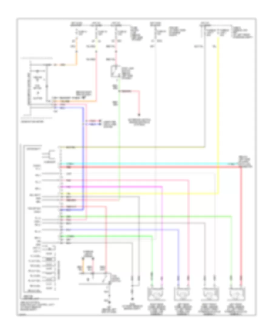
Anti-lock Brakes Wiring Diagram, with Traction Control & Stability Assist (1 of 2) for Nissan Quest 2006

List of elements for Anti-lock Brakes Wiring Diagram, with Traction Control & Stability Assist (1 of 2) for Nissan Quest 2006:
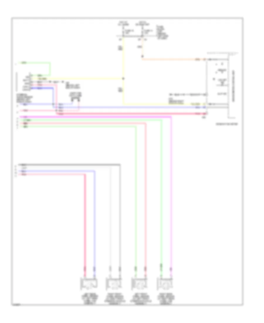
Anti-lock Brakes Wiring Diagram, with Traction Control & Stability Assist (2 of 2) for Nissan Quest 2006
List of elements for Anti-lock Brakes Wiring Diagram, with Traction Control & Stability Assist (2 of 2) for Nissan Quest 2006:
Anti-lock Brakes Wiring Diagram, with Traction Control for Nissan Quest 2006
List of elements for Anti-lock Brakes Wiring Diagram, with Traction Control for Nissan Quest 2006: