INSTRUMENT CLUSTER
Instrument Cluster Wiring Diagram (1 of 2) for Nissan Quest 2006

List of elements for Instrument Cluster Wiring Diagram (1 of 2) for Nissan Quest 2006:
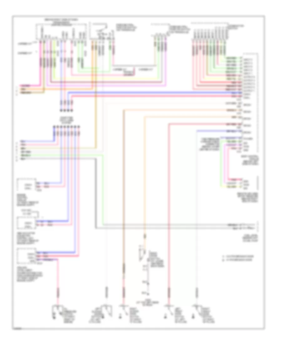
Instrument Cluster Wiring Diagram (2 of 2) for Nissan Quest 2006
List of elements for Instrument Cluster Wiring Diagram (2 of 2) for Nissan Quest 2006: