ANTI-LOCK BRAKES
Anti-lock Brake Wiring Diagrams, with Traction Control for Toyota Supra 1994

List of elements for Anti-lock Brake Wiring Diagrams, with Traction Control for Toyota Supra 1994:
- A10
- A11
- A12
- A13
- A14
- A15
- A16
- A17
- A18
- A19
- A20
- A21
- A22
- A23
- A24
- A25
- A26
- Abs #1 60a
- Abs #2 30a
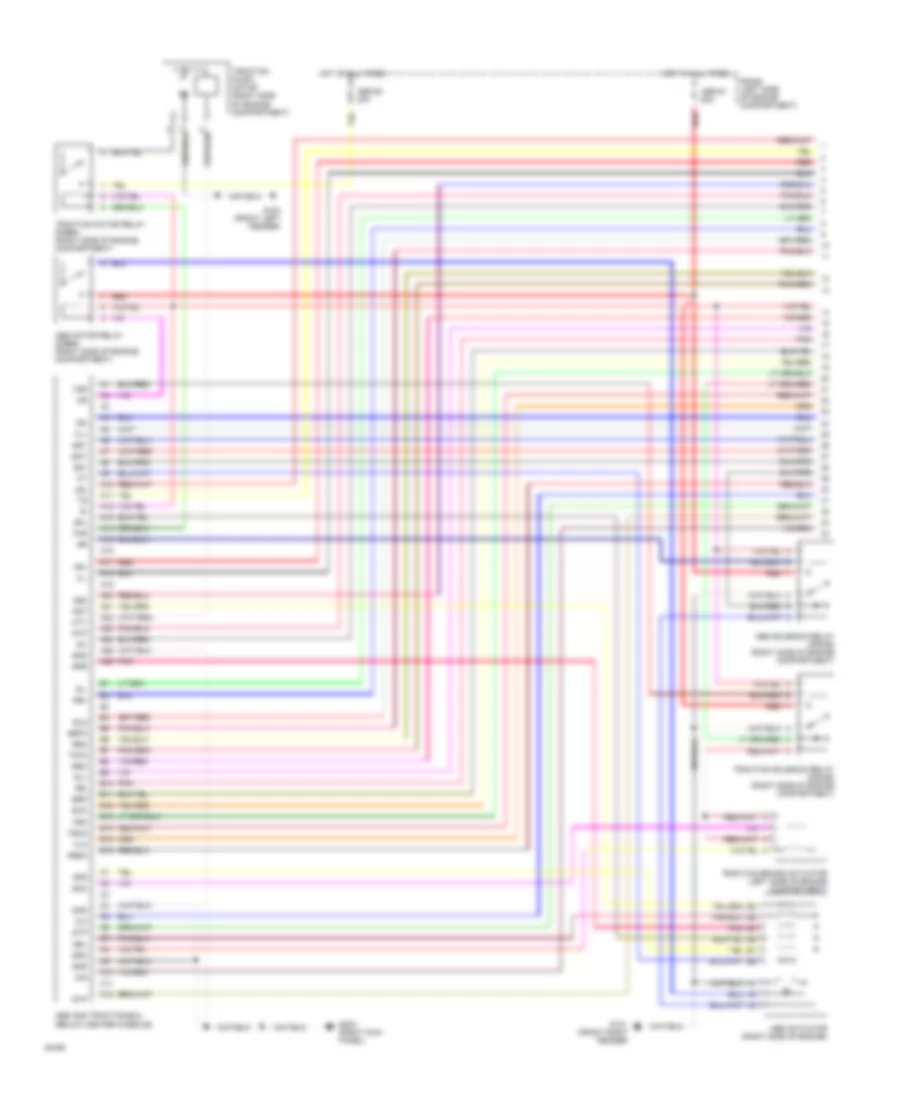
- Abs actuator (right side of engine)
- Abs and traction ecu (below center console)
- Abs motor relay (r/b#5) (right side of engine compartment)
- Abs solenoid relay (r/b #5) (right side of engine compartment)
- Abso
- Ast
- B10
- B11
- B12
- B13
- B14
- B15
- B16
- Bat
- Brc
- Brfa
- Brp
- C10
- C11
- C12
- D/g
- Exo
- Fl+
- Fl-
- Flo
- Fr+
- Fr-
- Fro
- G100 (front left fender)
- G101 (front right fender)
- G203 (right kick panel)
- Gnd
- Gs1
- Gs2
- Gst
- Hot at all times
- Ig1
- Lbl
- Mtt
- Pnk
- R/b #2 (left side of engine compartment)
- Red
- Rl+
- Rl-
- Rld
- Rr+
- Rr-
- Rro
- Sfl
- Sfr
- Smc
- Src
- Srl
- Srr
- Stp
- Thfa
- Tmr
- Traction brake actuator (left side of engine compartment)
- Traction motor relay (r/b#5) (right side of engine compartment)
- Traction pump/ motor (right side of engine compartment)
- Traction solenoid relay (r/b #5) (right side of engine compartment)
- Trco
- Tsr
Anti-lock Brake Wiring Diagrams, with Traction Control (1 of 3) for Toyota Supra 1994
List of elements for Anti-lock Brake Wiring Diagrams, with Traction Control (1 of 3) for Toyota Supra 1994:
- A10
- A11
- A12
- A13
- A14
- A15
- A16
- A17
- A18
- A19
- A20
- A21
- A22
- A23
- A24
- A25
- A26
- Abs #1 60a
- Abs #2 30a
- Abs actuator (right side of engine)
- Abs and traction ecu (below center console)
- Abs motor relay (r/b#5) (right side of engine compartment)
- Abs solenoid relay (r/b #5) (right side of engine compartment)
- Abso
- Ast
- B10
- B11
- B12
- B13
- B14
- B15
- B16
- Bat
- Brc
- Brfa
- Brp
- C10
- C11
- C12
- D/g
- Exo
- Fl+
- Fl-
- Flo
- Fr+
- Fr-
- Fro
- G100 (front left fender)
- G101 (front right fender)
- G203 (right kick panel)
- Gnd
- Gs1
- Gs2
- Gst
- Hot at all times
- Ig1
- Lbl
- Mtt
- Pnk
- R/b #2 (left side of engine compartment)
- Red
- Rl+
- Rl-
- Rld
- Rr+
- Rr-
- Rro
- Sfl
- Sfr
- Smc
- Src
- Srl
- Srr
- Stp
- Thfa
- Tmr
- Traction brake actuator (left side of engine compartment)
- Traction motor relay (r/b#5) (right side of engine compartment)
- Traction pump/ motor (right side of engine compartment)
- Traction solenoid relay (r/b #5) (right side of engine compartment)
- Trco
- Tsr
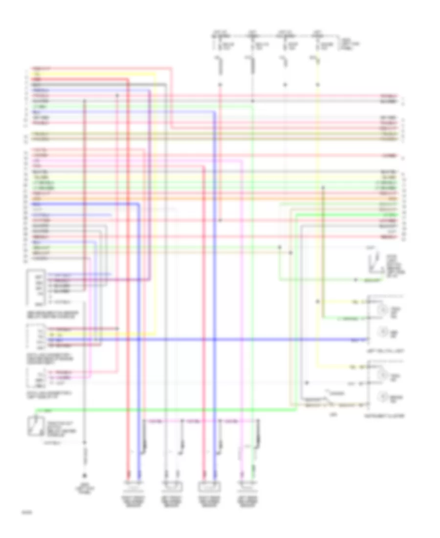
Anti-lock Brake Wiring Diagrams, with Traction Control (2 of 1) for Toyota Supra 1994
List of elements for Anti-lock Brake Wiring Diagrams, with Traction Control (2 of 1) for Toyota Supra 1994:
- +ig
- Abs
- Abs deceleration sensor (below center console)
- Abs ind
- Brake ind
- Canada
- Data link connector 1 (center rear of engine compartment)
- Data link connector 2 (left side of i/p)
- Ecu-1g 10a
- Ecu-b 10a
- G200 (left kick panel)
- Gauge 10a
- Gnd
- Gs1
- Gs2
- Gst
- Hot at all times
- Hot in run
- Instrument cluster
- J/b #1 (left kick panel)
- Left front abs speed sensor
- Left rear abs speed sensor
- Left telltail light
- Nca
- Pnk
- Red
- Right front abs speed sensor
- Right rear abs speed sensor
- Stop 15a
- Stop light switch (behind left side of i/p)
- Trac ind
- Trac off ind
- Traction cut switch (below center console)
- Trc
- Usa
Anti-lock Brake Wiring Diagrams, with Traction Control (2 of 3) for Toyota Supra 1994
List of elements for Anti-lock Brake Wiring Diagrams, with Traction Control (2 of 3) for Toyota Supra 1994:
- +ig
- Abs
- Abs deceleration sensor (below center console)
- Abs ind
- Brake ind
- Canada
- Data link connector 1 (center rear of engine compartment)
- Data link connector 2 (left side of i/p)
- Ecu-1g 10a
- Ecu-b 10a
- G200 (left kick panel)
- Gauge 10a
- Gnd
- Gs1
- Gs2
- Gst
- Hot at all times
- Hot in run
- Instrument cluster
- J/b #1 (left kick panel)
- Left front abs speed sensor
- Left rear abs speed sensor
- Left telltail light
- Nca
- Pnk
- Red
- Right front abs speed sensor
- Right rear abs speed sensor
- Stop 15a
- Stop light switch (behind left side of i/p)
- Trac ind
- Trac off ind
- Traction cut switch (below center console)
- Trc
- Usa
Anti-lock Brake Wiring Diagrams, with Traction Control (3 of 1) for Toyota Supra 1994
List of elements for Anti-lock Brake Wiring Diagrams, with Traction Control (3 of 1) for Toyota Supra 1994:
- A10
- A11
- A12
- A13
- A14
- A15
- A16
- A17
- A18
- A19
- A20
- A21
- A22
- A23
- A24
- A25
- A26
- A27
- A38
- Abs
- Abso
- Acm
- B10
- B11
- B12
- B41
- B42
- B63
- B64
- B65
- Bat
- Bcm
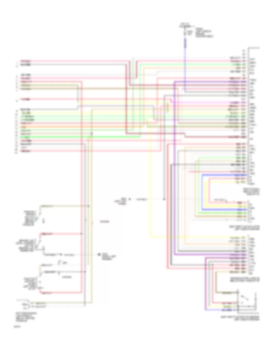
- Brake fluid level warning switch (brake fluid reservoir)
- Brc
- Brfa
- Brp
- Canada
- Csw
- Daytime running lights relay (below center console)
- Efi+
- Efi-
- Engine control module (below right side of i/p)
- Flo
- Fro
- G100 (front left fender)
- G200 (left kick panel)
- Gnd
- Hot at all times
- Idl1
- Idl2
- Ig1
- Ind
- Neo
- Oil
- Parking brake switch (below center console)
- Pkb
- R/b #2 (left side of engine compartment)
- Red
- Rlo
- Rro
- Stp
- Sub throttle actuator (left side of engine)
- Sub throttle position sensor (left side of engine)
- Thfa
- Trac 7.5a
- Traction control diode (left side of i/p)
- Traction ecu (below right side of i/p)
- Trc+
- Trc-
- Trco
- Usa
- Vcc
- Vta2
Anti-lock Brake Wiring Diagrams, with Traction Control (3 of 3) for Toyota Supra 1994
List of elements for Anti-lock Brake Wiring Diagrams, with Traction Control (3 of 3) for Toyota Supra 1994:
- A10
- A11
- A12
- A13
- A14
- A15
- A16
- A17
- A18
- A19
- A20
- A21
- A22
- A23
- A24
- A25
- A26
- A27
- A38
- Abs
- Abso
- Acm
- B10
- B11
- B12
- B41
- B42
- B63
- B64
- B65
- Bat
- Bcm
- Brake fluid level warning switch (brake fluid reservoir)
- Brc
- Brfa
- Brp
- Canada
- Csw
- Daytime running lights relay (below center console)
- Efi+
- Efi-
- Engine control module (below right side of i/p)
- Flo
- Fro
- G100 (front left fender)
- G200 (left kick panel)
- Gnd
- Hot at all times
- Idl1
- Idl2
- Ig1
- Ind
- Neo
- Oil
- Parking brake switch (below center console)
- Pkb
- R/b #2 (left side of engine compartment)
- Red
- Rlo
- Rro
- Stp
- Sub throttle actuator (left side of engine)
- Sub throttle position sensor (left side of engine)
- Thfa
- Trac 7.5a
- Traction control diode (left side of i/p)
- Traction ecu (below right side of i/p)
- Trc+
- Trc-
- Trco
- Usa
- Vcc
- Vta2
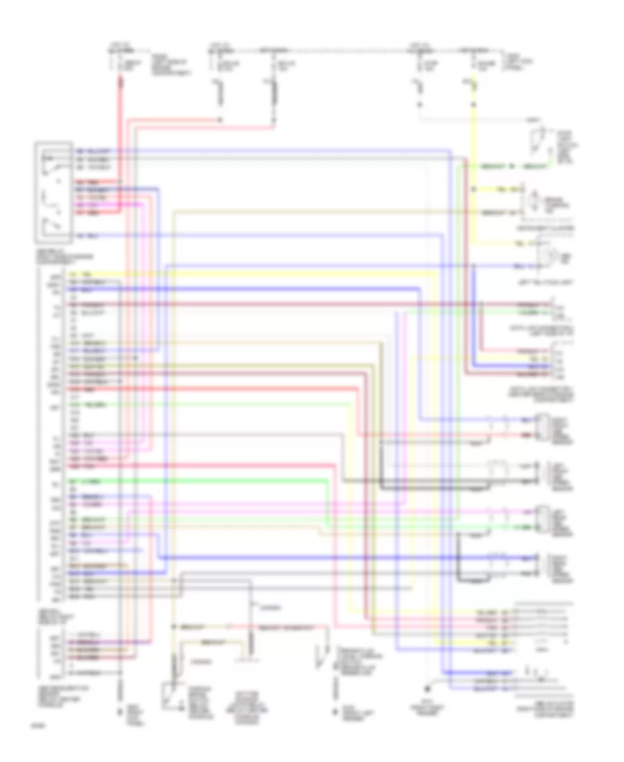
Anti-lock Brake Wiring Diagrams, without Traction Control for Toyota Supra 1994
List of elements for Anti-lock Brake Wiring Diagrams, without Traction Control for Toyota Supra 1994:
- +ig
- A10
- A11
- A12
- A13
- A14
- A15
- A16
- A17
- A18
- A19
- A20
- A21
- A22
- A23
- A24
- A25
- A26
- Abs #1 60a
- Abs actuator (right side of engine compartment)
- Abs deceleration sensor (below center console)
- Abs ecu (below right side of i/p)
- Abs ind
- Abs relay (right side of engine compartment)
- Ast
- B10
- B11
- B12
- B13
- B14
- B15
- B16
- Bat
- Brake fluid level warning switch (brake fluid reservoir)
- Brake warning ind
- Canada
- D/g
- Data link connector 1 (center rear of engine compartment)
- Data link connector 2 (left side of i/p)
- Daytime running lights relay (below center console) (canada)
- Ecu-b 10a
- Ecu-ig 10a
- Fl+
- Fl-
- Fr+
- Fr-
- Fss
- G100 (front left fender)
- G101 (front right fender)
- G203 (right kick panel)
- Gauge 10a
- Gnd
- Gnd1
- Gnd2
- Gs1
- Gs2
- Gst
- Hot at all times
- Hot in run
- Ig1
- Instrument cluster
- J/b #1 (left kick panel)
- Left front abs speed sensor
- Left rear abs speed sensor
- Left telltale light
- Nca
- Parking brake switch (below center console)
- Pkb
- Pnk
- R/b #2 (left side of engine compartment)
- Red
- Right front abs speed sensor
- Right rear abs speed sensor
- Rl+
- Rl-
- Rr+
- Rr-
- Rss
- Sfl
- Sfr
- Srl
- Srr
- Stop 15a
- Stop light switch (left side of i/p)
- Stp