
AIR CONDITIONING
A/C Wiring Diagram (1 of 2) for Toyota Supra 1994

List of elements for A/C Wiring Diagram (1 of 2) for Toyota Supra 1994:
A/C Wiring Diagram (2 of 2) for Toyota Supra 1994
List of elements for A/C Wiring Diagram (2 of 2) for Toyota Supra 1994:
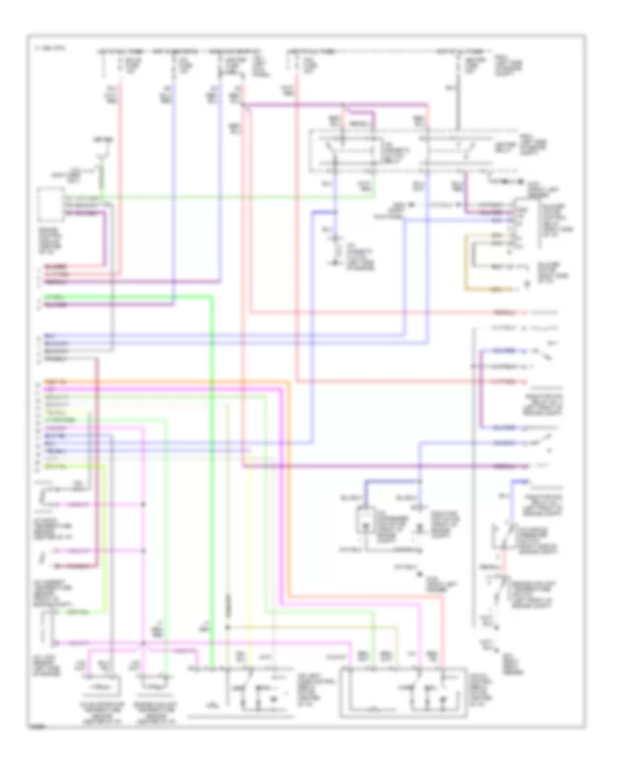
Air Conditioning Wiring Diagrams (1 of 2) for Toyota Supra 1994
List of elements for Air Conditioning Wiring Diagrams (1 of 2) for Toyota Supra 1994:
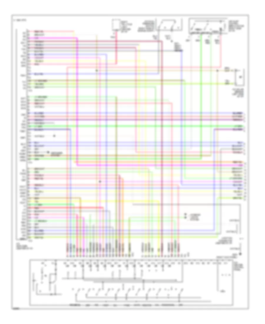
Air Conditioning Wiring Diagrams (2 of 2) for Toyota Supra 1994
List of elements for Air Conditioning Wiring Diagrams (2 of 2) for Toyota Supra 1994:
