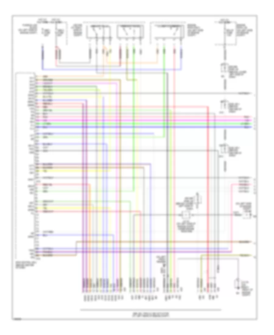
ANTI-LOCK BRAKES
Anti-lock Brakes Wiring Diagram, Access/Standard Cab without VSC for Toyota Tundra Limited 2004

List of elements for Anti-lock Brakes Wiring Diagram, Access/Standard Cab without VSC for Toyota Tundra Limited 2004:
- (behind upper left side of dash, near instrument cluster) (a/t) diode
- +bm
- +bs
- 4.7l, 3.4l a/t
- A j23
- A j24
- Abs 2 fuse 40a
- Abs 3 fuse 40a
- Abs actuator with ecu (in right rear corner of engine compartment)
- Abs deceleration sensor (under front of center console)
- Abs ind
- Acc fuse 15a
- Active circuit
- C11
- C13
- Combination meter (abs warning light)
- Control circuit
- D/g
- Data link connector 3 (below left side of dash, near center console)
- Driver side j/b (behind lower left side of dash)
- Ecu ig fuse 5a
- Engine room r/b (on left side of engine compt)
- Exi
- Exi4
- Fl+
- Fl-
- Fr+
- Fr-
- G11
- Gauge fuse 10a
- Ggnd
- Gl1
- Gnd1
- Gnd2
- Hot at all times
- Hot in on or acc
- Hot in on or start
- I18
- Ie (behind left kick panel)
- Ig1
- J/c 10 (behind upper left side of dash, near instrument cluster)
- J/c 13 (behind right kick panel)
- J/c 23 & 24 (behind left end of dash)
- J/c 28 & 29 (behind upper right side of dash, near passenger's air bag) j29
- J/c 5 (behind upper left side of dash, near instrument cluster)
- J/c 8 (behind upper left side of dash, near instrument cluster)
- J/c 9 (w/o keyless entry) (behind upper left side of dash, near instrument cluster)
- J28
- Left
- Left front abs speed sensor (at left front steering knuckle assembly)
- Nca
- Park/neutral position switch (a/t) (on transmission)
- Pnk
- Rear abs speed sensor (on left side of rear axle)
- Red
- Right
- Right front abs speed sensor (at right front steering knuckle assembly)
- Rl+
- Rl-
- Rr+
- Rr-
- Sil
- Spi
- Stop fuse 15a
- Stoplight switch (on bracket, above brake pedal)
- Stp
- Transmissions system
- Vgs
- W/ keyless entry
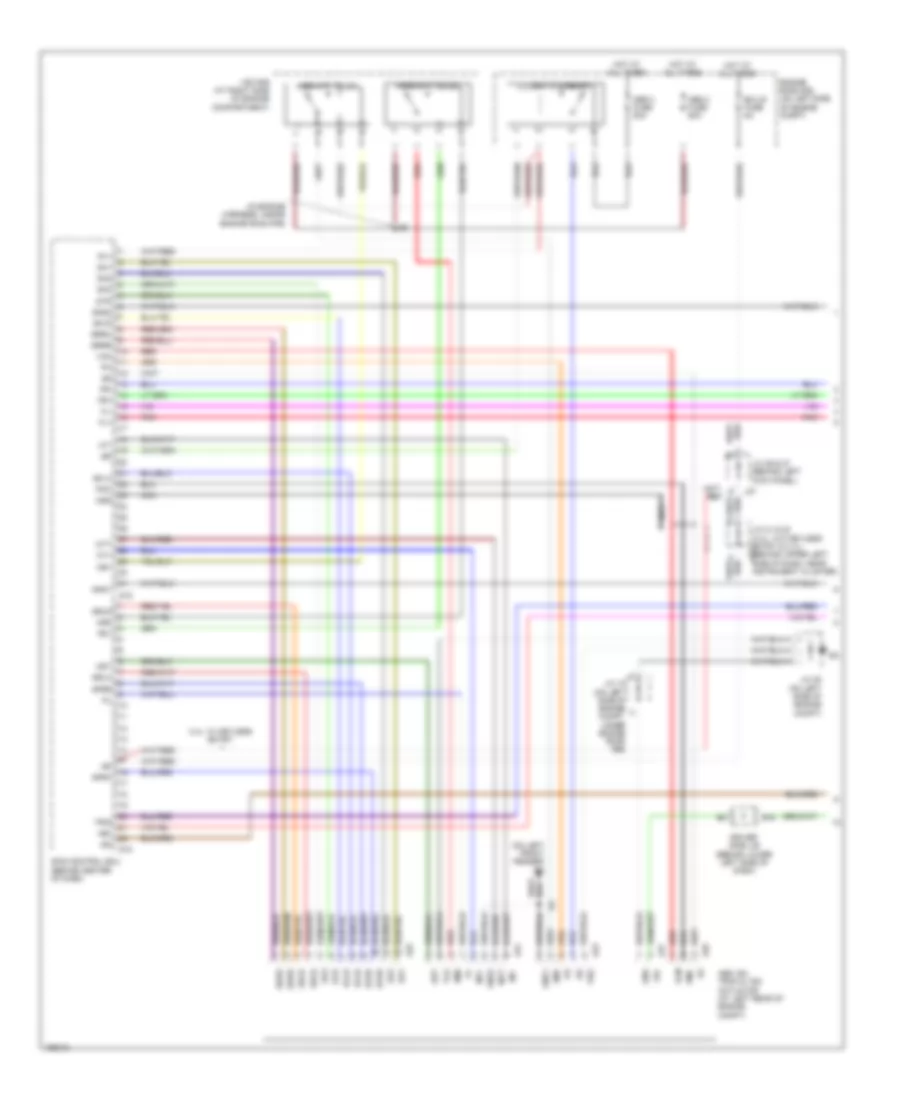
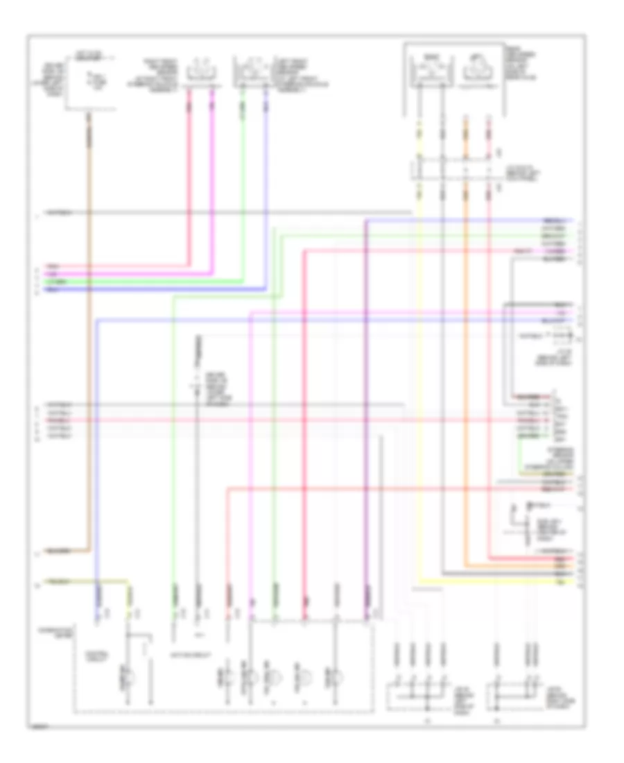
Anti-lock Brakes Wiring Diagram, Access/Standard Cab withVSC (1 of 3) for Toyota Tundra Limited 2004
List of elements for Anti-lock Brakes Wiring Diagram, Access/Standard Cab withVSC (1 of 3) for Toyota Tundra Limited 2004:
- (in engine harness, inside
- (on left front fender) ea
- +bi
- +bo
- 3.4l: w/ keyless entry
- A23
- A24
- A25
- A26
- A27
- Abs 2 fuse 50a
- Abs 3 fuse 50a
- Abs mtr relay
- Abs sol relay
- Abs, ba, trac & vsc actuator (at left rear of engine compt)
- Ast
- B15
- Bm1
- Bm2
- Driver side j/b (behind lower left side of dash)
- Ecu b fuse 5a
- Engine room r/b (on left side of engine compt)
- Engine room r/b)
- F red
- Fl+
- Fl-
- Fr+
- Fr-
- Gnd
- Gnd1
- Gnd2
- Hot at all times
- Ig2
- J/c 18 (on left side of engine compt, under engine room r/b)
- J/c 21 & 22 (3.4l: w/o keyless entry & 4.7l) (behind upper left side of dash, near j22 instrument cluster)
- J/c 25 (on left side of engine compt)
- J/c 26 & 27 (behind left kick panel)
- J27
- Lbl
- Mr1
- Mr2
- Mss
- Mt+
- Mt-
- Mtt
- Nca
- Phg
- Plg
- Pmc
- Pnk
- R1+
- R2+
- Red
- S15
- S18
- Sa1
- Sa2
- Sa3
- Sflh
- Sflr
- Sfrh
- Sfrr
- Skid control ecu (behind center of dash)
- Srlh
- Srlr
- Srrh
- Srrr
- Str
- Trac mtr relay
- Trig
- Vcm
- Vsc r/b (at right side of engine compartment)
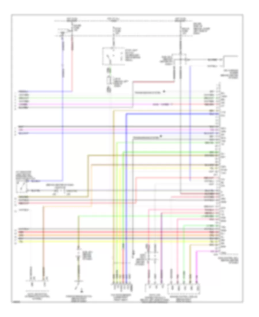
Anti-lock Brakes Wiring Diagram, Access/Standard Cab withVSC (2 of 3) for Toyota Tundra Limited 2004
List of elements for Anti-lock Brakes Wiring Diagram, Access/Standard Cab withVSC (2 of 3) for Toyota Tundra Limited 2004:
- (in dash harness, behind upper right side of dash) i4
- 4.7l, 3.4l: a/t
- Abs ind
- Active circuit
- Auto lsd ind
- Bat
- Brake ind
- C11
- C13
- Combination meter
- Control circuit
- Driver side j/b (behind lower left side of dash)
- Ess
- F11
- Hot in on or start
- Ie (behind left kick panel)
- Ign fuse 5a
- J/c 13 (behind right kick panel)
- J/c 23 & 24 (behind left end of dash)
- J/c 4 (behind left kick panel)
- J23
- J24
- Left
- Left front abs speed sensor (at left front steering knuckle assembly)
- Pnk
- Rear abs speed sensor (on left side of rear axle)
- Red
- Right
- Right front abs speed sensor (at right front steering knuckle assembly)
- Slip ind
- Ss1+
- Ss1-
- Steering sensor (on upper steering column)
- Trig
- Vsc off ind
- Vsc trac ind
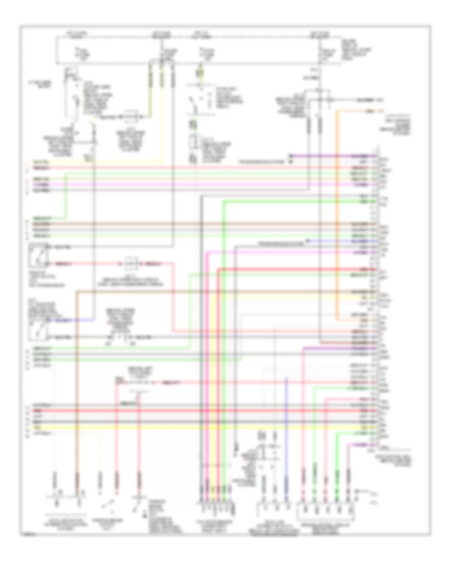
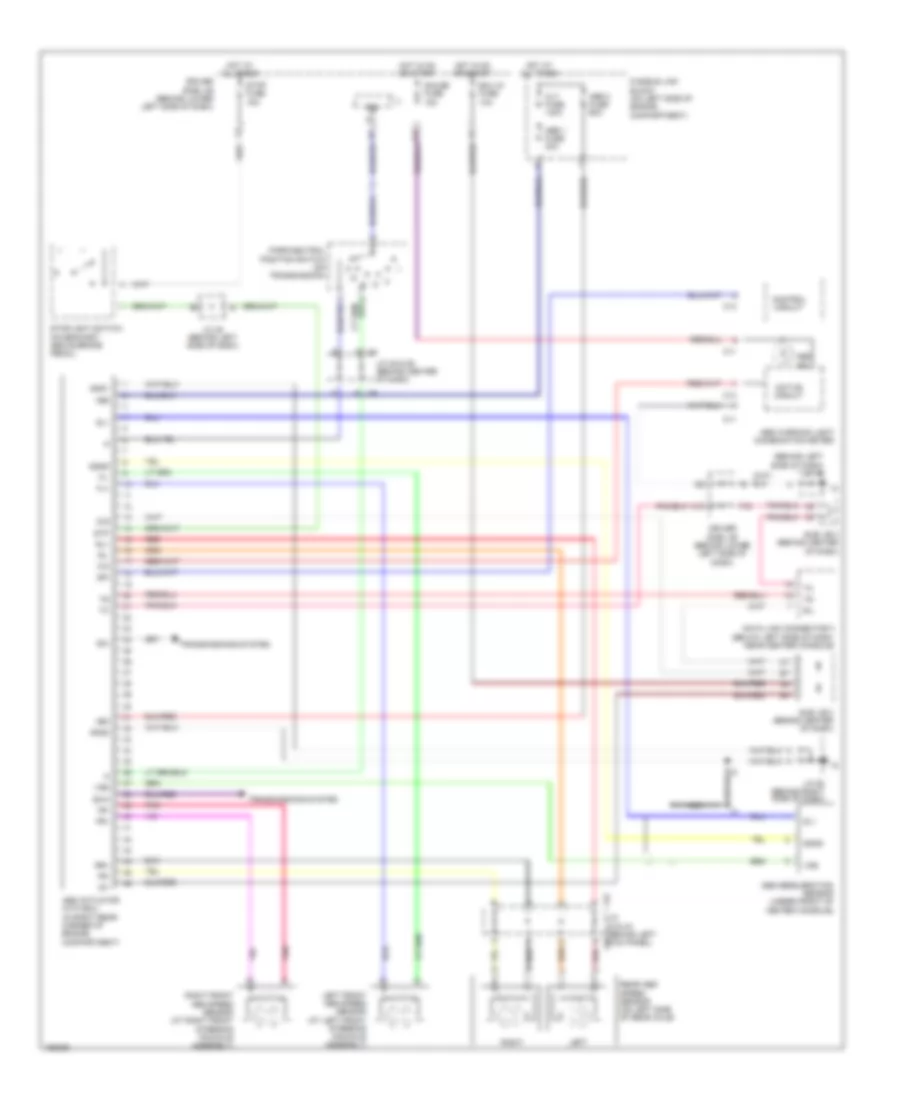
Anti-lock Brakes Wiring Diagram, Access/Standard Cab withVSC (3 of 3) for Toyota Tundra Limited 2004
List of elements for Anti-lock Brakes Wiring Diagram, Access/Standard Cab withVSC (3 of 3) for Toyota Tundra Limited 2004:
- (a/t) a/t indicator light switch (park/neutral position switch)
- (behind left kick panel) j/c 4
- (behind lower left side of dash)
- (behind upper right side of dash, near passenger's airbag) j/c 28 & 29
- 3.4l
- 4.7l
- Acc fuse 15a
- Auto lsd switch (integration control & panel)
- Back-up light switch (m/t) (on transmission)
- Brl
- Cpu
- Csw
- D/g
- Data link connector (dlc) 3 (below left side of dash, near center console)
- Diode (a/t) (behind upper left side of dash, near instrument cluster)
- Driver side j/b
- Ecu-ig fuse 5a
- Eng+
- Eng-
- Engine control module (behind right side of dash)
- Exi
- Exi2
- Exi4
- G11
- G13
- Gauge fuse 10a
- Gl1
- Gl2
- Gnd
- Gnd3
- Gnd4
- Gyaw
- Hot at all times
- Hot in acc or on
- Hot in on or start
- I24
- I25
- Ig1
- Ind
- Infr
- J/c 10 (behind upper left side of dash, near instrument cluster)
- J/c 11 (behind upper right side of dash, near passenger's airbag)
- J/c 12 (behind upper right side of dash, near passenger's airbag)
- J/c 5 (behind upper left side of dash, near instrument cluster)
- J/c 8 (behind upper left side of dash, near instrument cluster)
- J/c 9 (w/o keyless entry) (behind upper left side of dash, near instrument cluster)
- J28
- J29
- Nca
- Neo
- Parking brake switch (a/t) (on base of park brake pedal bracket, near kick panel)
- Parking brake switch (m/t)
- Pkb
- Pnk
- Red
- Rl+
- Rl-
- Rr+
- Rr-
- S16
- S17
- Sil
- Skid control ecu (behind center of dash)
- Spi
- Ss1+
- Ss1-
- Stop fuse 15a
- Stoplight switch (on bracket, above brake pedal)
- Stp
- Transmissions system
- Trc+
- Trc-
- Vsc warning buzzer (behind center of dash)
- Vscw
- Vys
- W/ keyless entry
- Yaw
- Yaw rate sensor (under right front seat)
- Yaw2
- Yss
Anti-lock Brakes Wiring Diagram, Double Cab with VSC (1 of 3) for Toyota Tundra Limited 2004
List of elements for Anti-lock Brakes Wiring Diagram, Double Cab with VSC (1 of 3) for Toyota Tundra Limited 2004:
- (on left front fender) ea
- (on left side of engine compt) j/c 35
- +bi
- +bo
- A19
- A23
- A24
- A25
- A26
- A27
- Abs 1 fuse 50a
- Abs 2 fuse 60a
- Abs mtr relay
- Abs sol relay
- Abs, ba, trac & vsc actuator (at left rear of engine compt)
- Ast
- Bm1
- Bm2
- D10
- Driver side j/b (behind lower left side of dash)
- E10
- Ecu b fuse 7.5a
- Engine room j/b (on left side of engine compt)
- Engine room r/b 2 (on left side of engine compt)
- Fl+
- Fl-
- Fr+
- Fr-
- Fusible link block (on left side of engine compt)
- Gnd
- Gnd1
- Gnd2
- Hot at all times
- Ig2
- J/c 30 (on right front of engine compt)
- J/c 34 (on left side of engine compt, under engine room r/b)
- K12
- Lbl
- Mr1
- Mr2
- Mss
- Mt+
- Mt-
- Mtt
- Nca
- Phg
- Plg
- Pmc
- Pnk
- R1+
- R2+
- Red
- S15
- S18
- Sa1
- Sa2
- Sa3
- Sflh
- Sflr
- Sfrh
- Sfrr
- Skid control ecu (behind center of dash)
- Srlh
- Srlr
- Srrh
- Srrr
- Str
- Sub j/b 3 (behind center of dash)
- Sub j/b 4 (behind center of dash)
- Trac mtr relay
- Trig
- Vcm
- Vsc r/b (at right side of engine compt)
Anti-lock Brakes Wiring Diagram, Double Cab with VSC (2 of 3) for Toyota Tundra Limited 2004
List of elements for Anti-lock Brakes Wiring Diagram, Double Cab with VSC (2 of 3) for Toyota Tundra Limited 2004:
- Abs ind
- Active circuit
- Auto lsd ind
- B10
- Bat
- Brake ind
- C11
- C13
- Combination meter
- Control circuit
- D10
- Driver side j/b (behind lower left side of dash)
- E17
- Ess
- Hot in on or start
- Ign 1 fuse 10a
- J/b 45 (behind left side of dash)
- J/b 58 (behind right side of dash)
- J/c 42 & 43 (behind left kick panel)
- J/c 45 (behind left side of dash)
- J42
- J43
- Left
- Left front abs speed sensor (at left front steering knuckle assembly)
- Pnk
- Rear abs speed sensor (on left side of rear axle)
- Red
- Right
- Right front abs speed sensor (at right front steering knuckle assembly)
- Slip ind
- Ss1+
- Ss1-
- Steering sensor (on upper steering column)
- Sub j/b 4 (behind center of dash)
- Trig
- Vsc off ind
- Vsc trac ind
Anti-lock Brakes Wiring Diagram, Double Cab with VSC (3 of 3) for Toyota Tundra Limited 2004
List of elements for Anti-lock Brakes Wiring Diagram, Double Cab with VSC (3 of 3) for Toyota Tundra Limited 2004:
- (4wd)
- (behind center of dash) j/c 28 & 29
- A/t indicator light switch (park/neutral position switch)
- A16
- Auto lsd switch (integration control & panel)
- Brl
- Cpu
- Csw
- D/g
- D12
- Data link connector (dlc) 3 (below left side of dash, near center console)
- Driver side j/b (behind lower left side of dash)
- Ecu-ig fuse 10a
- Eng+
- Eng-
- Engine control module (behind right side of dash)
- Exi
- Exi4
- Gauge fuse 15a
- Gl1
- Gl2
- Gnd
- Gnd3
- Gnd4
- Gyaw
- Hot at all times
- Hot in on or start
- I24
- I25
- Ig1
- Ind
- Infr
- Ipo
- J/b 48 (behind left side of dash)
- J28
- J29
- Nca
- Neo
- Parking brake switch (behind right side of dash)
- Pkb
- Pnk
- Red
- Rl+
- Rl-
- Rr+
- Rr-
- S16
- S17
- Sil
- Skid control ecu (behind center of dash)
- Spi
- Ss1+
- Ss1-
- Stop fuse 15a
- Stop light switch (on bracket, above brake pedal)
- Stp
- Sub j/b 3 (behind center of dash)
- Transmissions system
- Trc+
- Trc-
- Vsc warning buzzer (behind center of dash)
- Vscw
- Vys
- Yaw
- Yaw rate sensor (under right front seat)
- Yaw2
- Yss
Anti-lock Brakes Wiring Diagram, Double Cab without VSC for Toyota Tundra Limited 2004
List of elements for Anti-lock Brakes Wiring Diagram, Double Cab without VSC for Toyota Tundra Limited 2004:
- (behind left side of dash) j/c 45
- +bm
- +bs
- Abs 1 fuse 30a
- Abs 2 fuse 60a
- Abs actuator with ecu (in right rear corner of engine compartment)
- Abs deceleration sensor (under front of center console)
- Abs ind
- Abs warning light (combination meter)
- Active circuit
- Alt fuse 140a
- C11
- C13
- Control circuit
- D/g
- D12
- Data link connector 3 (below left side of dash, near center console)
- Driver side j/b (behind lower left side of dash)
- Ecu ig fuse 10a
- Exi
- Exi4
- F15
- Fl+
- Fl-
- Fr+
- Fr-
- Fusible link block (on left side of engine compartment)
- G j29
- Gauge fuse 15a
- Ggnd
- Gl1
- Gnd1
- Gnd2
- Hot at all times
- Hot in on or start
- Ig1
- Ipo
- J/c 28 & 29 (behind center of dash)
- J/c 48 (behind left side of dash)
- J/c 58 (behind right side of dash)
- J28
- J42 j/c 42 & 43 (behind left j43 kick panel)
- K10
- Left
- Left front abs speed sensor (at left front steering knuckle assembly)
- Nca
- Park/neutral position switch (on transmission)
- Pnk
- Rear abs speed sensor (on left side of rear axle)
- Red
- Right
- Right front abs speed sensor (at right front steering knuckle assembly)
- Rl+
- Rl-
- Rr+
- Sil
- Spi
- Stop fuse 15a
- Stoplight switch (on bracket, above brake pedal)
- Stp
- Sub j/b 3 (behind center of dash)
- Transmissions system
- Vgs