
ANTI-LOCK BRAKES
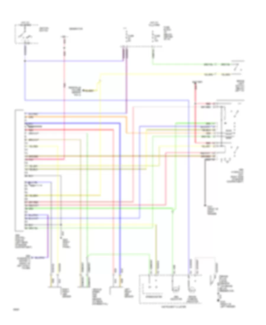
Anti-lock Brake Wiring Diagrams for Volvo 960 1994
List of elements for Anti-lock Brake Wiring Diagrams for Volvo 960 1994:
AIR CONDITIONINGANTI-LOCK BRAKESANTI-THEFTCOMPUTER DATA LINESCOOLING FANCRUISE CONTROLDEFOGGERSENGINE PERFORMANCEEXTERIOR LIGHTSGROUND DISTRIBUTIONHEADLIGHTSHORNINSTRUMENT CLUSTERINTERIOR LIGHTSMEMORY SYSTEMSPOWER ANTENNAPOWER DISTRIBUTIONPOWER DOOR LOCKSPOWER MIRRORSPOWER SEATSPOWER TOP/SUNROOFPOWER WINDOWSRADIOSHIFT INTERLOCKSSTARTING/CHARGINGSUPPLEMENTAL RESTRAINTSTRANSMISSIONWARNING SYSTEMSWIPER/WASHER