ANTI-THEFT
Forced Entry Wiring Diagram, Accessory for Honda Accord DX 2004

List of elements for Forced Entry Wiring Diagram, Accessory for Honda Accord DX 2004:
- (lx) (usa: dx)
- (not used)
- (usa: dx) (lx)
- Body controller area network transceiver
- Ceiling light
- Driver's door switch
- E14
- E15
- Front passenger's door switch
- Fuse 7.5a
- G20 (behind middle of front bumper)
- G51 (behind left kick panel)
- G701 (sedan: at left side of trunk)
- Gauge control module
- H12
- H13
- Hot at all times
- Hot in run
- Left rear door switch
- Microphone
- Micu
- N28
- Off
- P24
- Rear junction block
- Right rear door switch
- Security control unit (under left side of dash)
- Security hood switch (at front of engine compt, on hood lock/latch assembly)
- Security inline fuse
- Security receiver unit (dx)
- Sedan
- Trunk latch switch (coupe: at middle rear of trunk lid)
- Trunk light
- Trunk switch
- Under-dash fuse/relay box (behind left kick panel)
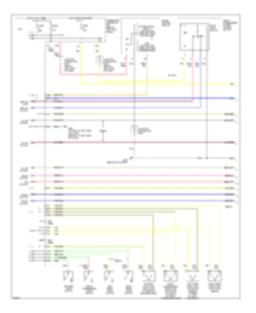
Forced Entry Wiring Diagram, Factory Installed (1 of 2) for Honda Accord DX 2004
List of elements for Forced Entry Wiring Diagram, Factory Installed (1 of 2) for Honda Accord DX 2004:
- (not used)
- D11
- Door lock switch
- Driver's door lock actuator (at rear of driver's door)
- Driver's door switch
- E10
- E14
- E15
- Ex, ex-l
- Fast controller area network transceiver
- Front passenger's door lock actuator (in middle of front passenger's door)
- Front passenger's door switch
- Front passenger's power window switch
- Fuse 10a
- Fuse 20a
- Fuse 7.5a
- G503 (behind glove box)
- G601 (coupe: on left side of floor) (sedan: at left side of floor)
- Gauge control module
- H10
- H12
- H13
- Hot at all times
- Hot in run or start
- Ign switch
- Junction connector c404
- Junction connector c405 (below left side of dash)
- K11
- K12
- Left rear door lock actuator (sedan) (at rear of left rear door)
- Left rear door switch
- Micu
- N28
- P11
- P13
- P24
- P25
- Radio switch
- Rem as lock
- Rem as unlock
- Right rear door lock actuator (sedan)
- Right rear door switch
- Sedan
- Sil as unlock
- Sil ra unlock
- Sil rd unlock
- Trunk switch
- Trunk unlock
- Under-dash fuse/relay box (behind left kick panel)
- Unlk
- X34
- X35
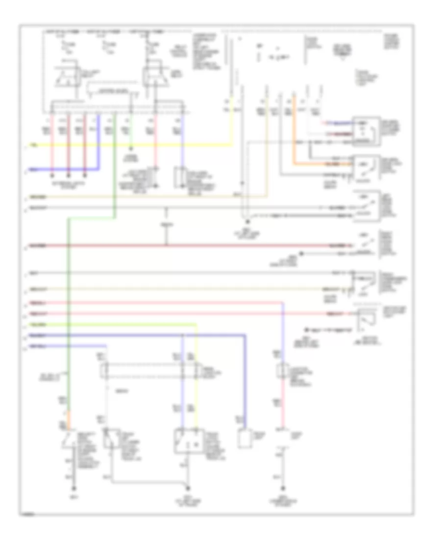
Forced Entry Wiring Diagram, Factory Installed (2 of 2) for Honda Accord DX 2004
List of elements for Forced Entry Wiring Diagram, Factory Installed (2 of 2) for Honda Accord DX 2004:
- A20
- Audio unit
- Control block
- Coupe sedan
- Door lock switch
- Door multiplex control unit
- Driver's door key cylinder switch
- Driver's door lock knob switch
- Ex, ex-l & canada lx
- Exterior lights system
- Front passenger's door lock knob switch
- Fuse 15a
- Fuse 20a
- Fuse 7.5a
- G201
- G501 (behind left side of dash)
- G504 (under middle of dash)
- G601 (at left side of floor)
- G602 (at right side of floor)
- G701 (at left side of trunk)
- H13
- H14
- High horn (at front of engine compartment, behind front grille)
- Horn relay
- Horns system
- Hot at all times
- Ignition key switch
- Ignition key switch/key light
- Junction connector c557 (behind glove box)
- Keyless receiver antenna
- Left rear door lock knob switch
- Lock
- Low horn (at front of engine compartment, behind front grille)
- Power window master switch
- Rear junction block
- Relay control module
- Right rear door lock knob switch
- Security hood switch (at front of engine compt, on hood lock/latch assembly)
- Sedan
- Taillight relay
- Trunk key cylinder switch (at right side of trunk lid)
- Trunk latch switch (coupe: at middle rear of trunk lid)
- Trunk light
- Under-hood fuse/relay box (on left rear corner of engine compt, forward of strut tower)
- Unlk
- Unlock
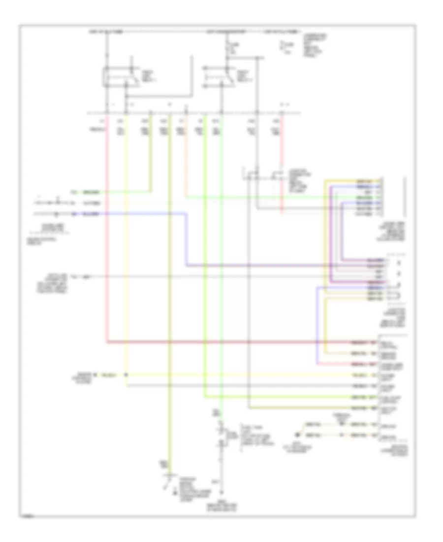
2.4L
2.4L, Immobilizer Wiring Diagram for Honda Accord DX 2004
List of elements for 2.4L, Immobilizer Wiring Diagram for Honda Accord DX 2004:
- (terminal joint) t13
- Data link connector (on lower left of dash, above the kick panel)
- E13
- E17
- E27
- Ecm/pcm (under middle of dash)
- Engine controls system
- Fuel pump
- Fuel pump control
- Fuel tank unit (in top of fuel tank, at left front of trunk)
- Fuse 10a
- Fuse 15a
- G101 (at top middle of engine)
- G603 (behind center of rear seats)
- Gauge control module
- Ground
- Hot at all times
- Hot in run or start
- Ignition input
- Immobilizer code input
- Immobilizer control unit -receiver (in steering column cover)
- Immobilizer system ind
- Junction connector c405 (below left side of dash)
- Junction connector c406 (below left side of dash)
- N30
- N34
- Parking brake switch (mounted under parking brake lever)
- Pgm-fi main relay 1
- Pgm-fi main relay 2
- Power input
- Relay control
- Sensor ground
- Under-dash fuse/relay box (behind left kick panel)
- X31
- X35
- X38
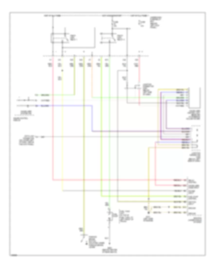
3.0L
3.0L, Immobilizer Wiring Diagram for Honda Accord DX 2004
List of elements for 3.0L, Immobilizer Wiring Diagram for Honda Accord DX 2004:
- A25
- B15
- Data link connector (on lower left of dash, above the kick panel)
- E13
- Ecm/pcm (under middle of dash)
- Fuel pump
- Fuel pump control
- Fuel tank unit (in top of fuel tank, at left front of trunk)
- Fuse 10a
- Fuse 15a
- G101 (left side of engine)
- G603 (behind center of rear seats)
- Gauge control module
- Ground
- Hot at all times
- Hot in run or start
- Ignition input
- Immobilizer code input
- Immobilizer control unit receiver (in steering column cover)
- Immobilizer system ind
- Junction connector c405 (below left side of dash)
- Junction connector c406 (below left side of dash)
- N30
- N34
- Parking brake switch (mounted under parking brake lever)
- Pgm-fi main relay 1
- Pgm-fi main relay 2
- Power input
- Relay control
- Under-dash fuse/relay box (behind left kick panel)
- X31
- X35
- X38