BODY CONTROL MODULES
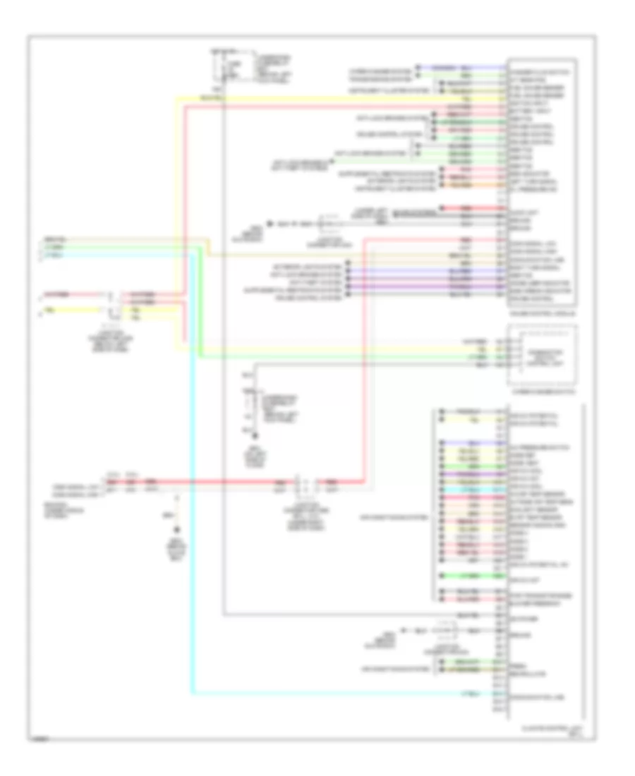
Body Control Modules Wiring Diagram (1 of 2) for Honda Accord DX 2004

List of elements for Body Control Modules Wiring Diagram (1 of 2) for Honda Accord DX 2004:
Body Control Modules Wiring Diagram (2 of 2) for Honda Accord DX 2004
List of elements for Body Control Modules Wiring Diagram (2 of 2) for Honda Accord DX 2004: