ANTI-THEFT
Forced Entry Wiring Diagram for Hyundai XG350 L 2004

List of elements for Forced Entry Wiring Diagram for Hyundai XG350 L 2004:
- (w/ ims)
- (w/o ims)
- 87a
- Assister door module (integral with power window/ door switch assembly, on right front door)
- Burglar alarm relay
- Code save
- D04
- D05
- D29
- D30
- Data
- Driver door module (integral with power window/ door switch assembly, on left front door)
- Drl control module (on right front of engine compartment, near engine mount)
- Drl fuse 15a
- Engine compartment junction block (on left front of engine compt)
- Etacm
- Exterior lights system
- Fuse 10a
- G01
- G03 (on left "a" pillar, near passenger compt junction block)
- G05 (on right "a" pillar, near crash bar)
- G07 (at left floorpanel crossmember)
- G08 (on left side of package shelf)
- G09 (on right side of package shelf)
- Haz rly cntrl
- Hazard relay
- Hood switch (on right front of engine compartment)
- Hood switch in
- Hot at all times
- Hot in start
- I/p-b
- I/p-p
- Je01
- Jm09
- Joint connector d12 (front of left front door)
- Joint connector d13 (front of right front door)
- Joint connector m99 (left side of trunk room)
- Left door unlock switch
- Left rear door lock actuator (rear of left rear door)
- M33-1
- M33-2
- M33-3
- Multipurpose check connector (at lower left side of dash)
- Nca
- Passenger compartment junction block (behind left end of dash)
- Rear dr input
- Red
- Relay box
- Relay control
- Right door unlock switch
- Right rear door lock actuator (rear of right rear door)
- Signal ground
- Siren (at right front corner of engine compartment)
- Siren control
- Starting/ charging system
- Trunk lid solenoid (on center of trunk, beside latch)
- Trunk lid unlock switch
- Trunk unlock switch in
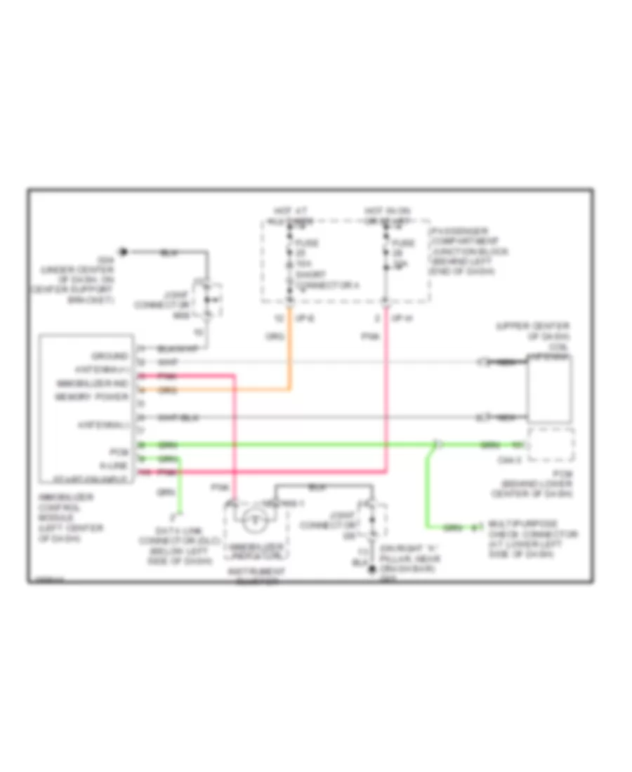
Immobilizer Wiring Diagram for Hyundai XG350 L 2004
List of elements for Immobilizer Wiring Diagram for Hyundai XG350 L 2004:
- (upper center of dash) coil antenna
- 118-1
- Antenna(+)
- Antenna(-)
- C44-3
- Crash bar) g05
- Data link connector (dlc) (below left side of dash)
- Fuse 10a
- G04 (under center of dash, on center support bracket)
- Ground
- Hot at all times
- Hot in on or start
- I/p-e
- I/p-h
- Immobilizer control module (left center of dash)
- Immobilizer ind
- Immobilizer indicator
- Instrument cluster
- Joint connector i28
- Joint connector m08
- K-line
- Memory power
- Multipurpose check connector (at lower left side of dash)
- Nca
- Passenger compartment junction block (behind left end of dash)
- Pcm
- Pcm (behind lower center of dash)
- Pnk
- Short connector a
- Start/on input