POWER DISTRIBUTION
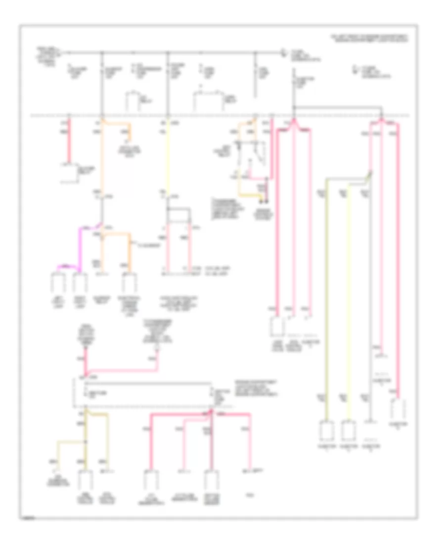
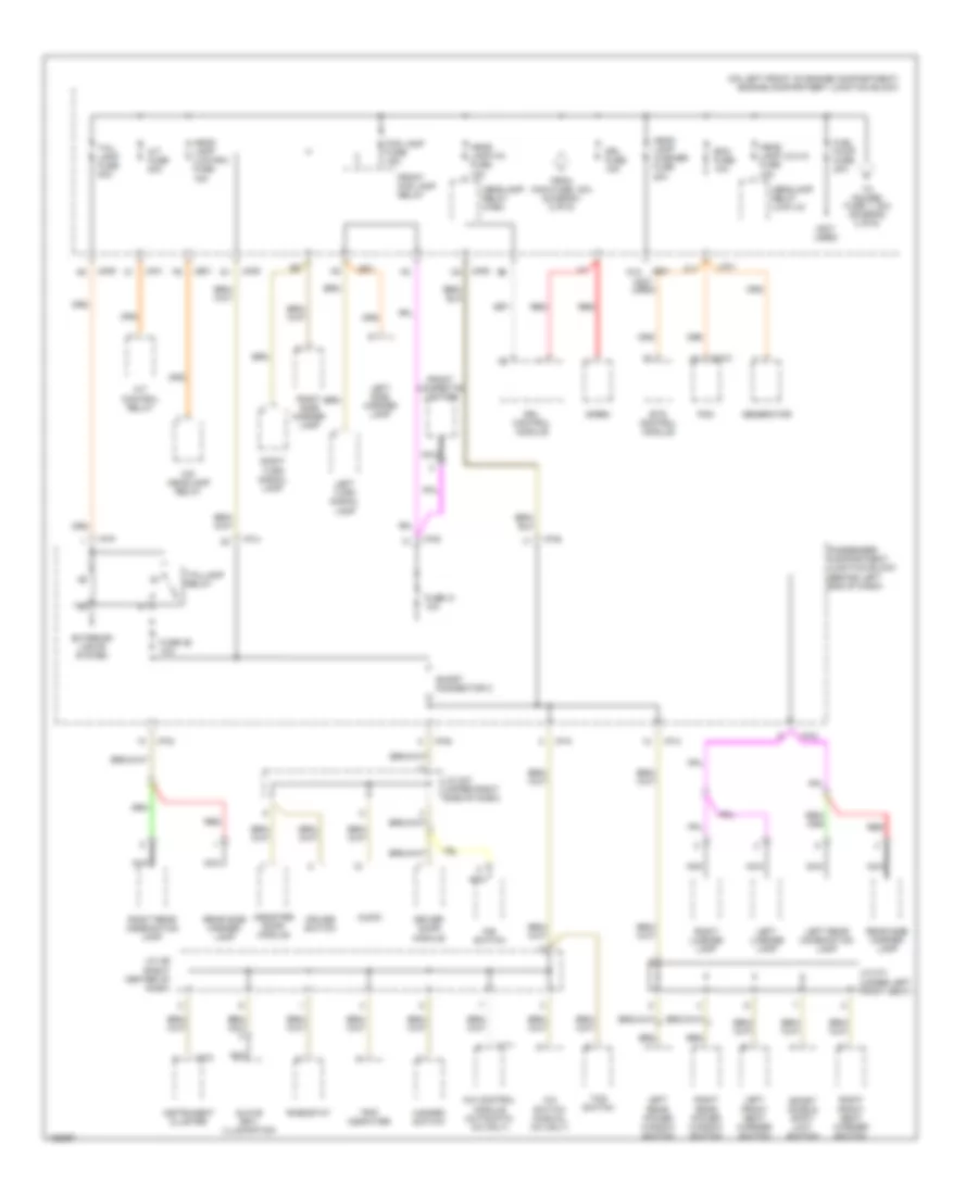
Power Distribution Wiring Diagram (1 of 6) for Hyundai XG350 L 2004

List of elements for Power Distribution Wiring Diagram (1 of 6) for Hyundai XG350 L 2004:
- (not used)
- (on left front of engine compartment) engine compartment junction block
- 87a
- A/c fan relay 1
- Abs control module
- Abs fusible link 1 30a
- Abs fusible link 2 30a
- Acc
- Accessory socket
- Air bleeding connector
- Ashtray illumination
- Audio
- Battery
- Battery ground
- Burglar alarm relay
- Condenser fusible link 20a
- Driver door module
- Electronic time & alarm control module (etacm)
- Engine compartment junction block (on left front of engine compt)
- Ets control module
- Front cigarette lighter
- Fuse 13 10a
- Fuse 14 10a
- Fuse 15 20a
- Fuse 16 10a
- Fuse 32 10a
- Fusible link 140a
- G03 (on left "a" pillar, near passenger compartment junction block)
- G07 (at left floor panel crossmember)
- Generator
- I/p-a
- I/p-b
- I/p-d
- I/p-e
- I/p-p
- Ignition fusible link 1 30a
- Ignition fusible link 2 30a
- Ignition switch
- Ims control module
- Ims switch
- Interior lights system
- J/c m08 (left center of dash)
- Jc01 b5
- Jco1
- Jm09
- Jm10
- Lock
- M110-1
- M33-3
- Nca
- Off
- Passenger compartment junction block (behind left end of dash)
- Pnk
- Power window fusible link 40a
- Power window relay
- Radiator fan relay
- Radiator fusible link 30a
- Rear accessory socket
- Red
- Rheostat
- Start
- Start motor
- Start relay
- Start solenoid
- To blower fuse, 30a (diagram 2 of 6)
- To engine compartment junction block (abs fuse, 10a) (diagram 2 of 6)
- To passenger compartment junction block (fuse 3, 10a) (diagram 5 of 6)
- Transaxle range switch
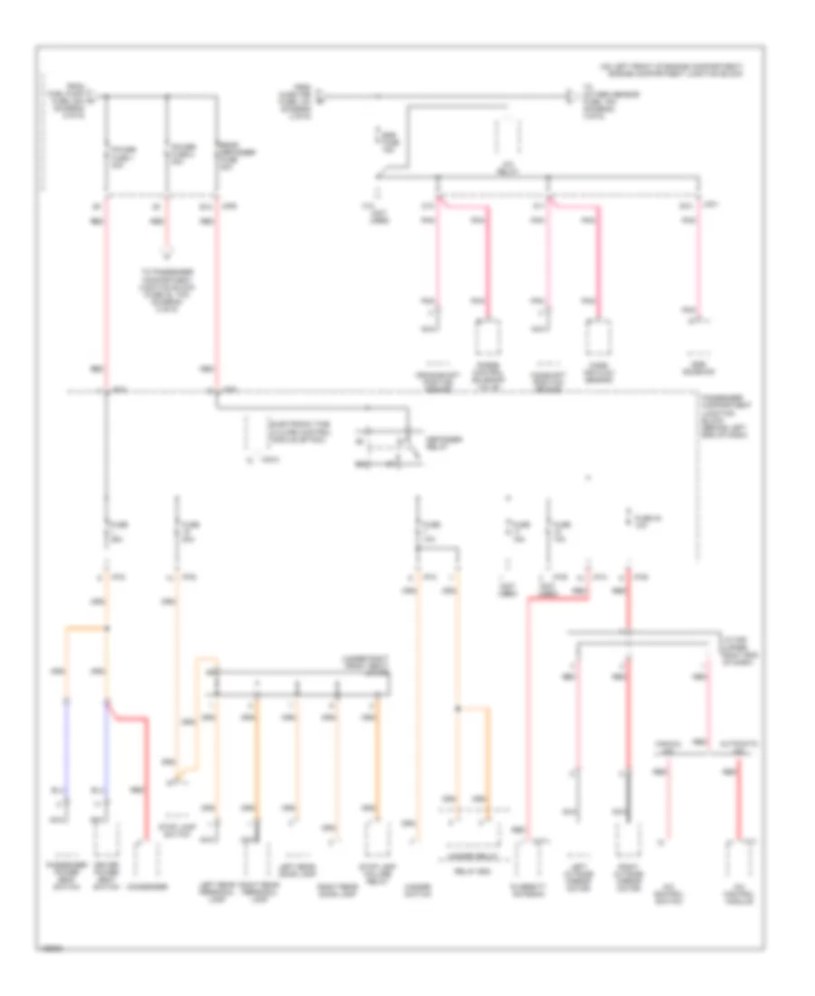
Power Distribution Wiring Diagram (2 of 6) for Hyundai XG350 L 2004
List of elements for Power Distribution Wiring Diagram (2 of 6) for Hyundai XG350 L 2004:
- (on left front of engine compartment) engine compartment junction block
- (w/ jbl amp)
- (w/o jbl amp)
- A/c compressor fuse 10a
- A/c relay
- A/t pulse generator-a
- A/t pulse generator-b
- Abs control module
- Abs fuse 10a
- Air bleeding connector
- Audio amp module 2 (w/o jbl amp) audio amp module 1 (w/ jbl amp)
- B10
- Blower fuse 30a
- Blower relay
- C44-3
- D12
- Data link connector (dlc)
- Ecm control relay
- Electrical chrome mirror (w/ home link)
- Engine compartment junction block (on left front of engine compartment)
- Engine controls system
- Ets control module
- F10
- F11
- From abs fusible a link 2, 30a (diagram 1 of 6)
- From ignition switch (diagram 1 of 6)
- Horn fuse 15a
- Horn relay
- I/p-a
- I/p-b
- I/p-e
- I/p-m
- Ignition coil fuse 20a
- Ignition failure sensor
- Injector
- Injector fuse 10a
- Jc01
- Jm09
- Lamp home valve
- Left vanity lamp
- M136
- M137
- Main fuse 30a
- Passenger compartment junction block (behind left end of dash)
- Pcm
- Pnk
- Power amp fuse 20a
- Red
- Right vanity lamp
- Sunroof fuse 15a
- Sunroof relay
- Tan
- To drl fuse, 15a (diagram 6 of 6)
- To egr fuse, 15a (diagram 3 of 6)
- To passenger compartment junction block (fuse 21, 10a) (diagram 4 of 6)
- W/ sunroof
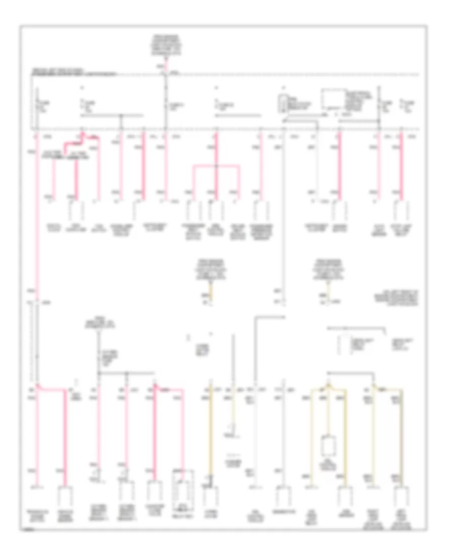
Power Distribution Wiring Diagram (3 of 6) for Hyundai XG350 L 2004
List of elements for Power Distribution Wiring Diagram (3 of 6) for Hyundai XG350 L 2004:
- (diagram 6 of 6)
- (not used)
- (on left front of engine compartment) engine compartment junction block
- (under right front seat) j/c m78
- A/c control module
- A/c control switch
- A/c relay
- Automatic a/c
- B12
- C10
- Camshaft position sensor
- Condenser
- Crankshaft position sensor
- D10
- D11
- Defogger relay
- Diversity antenna
- Driver power seat switch
- E10
- Egr fuse 15a
- Egr solenoid
- Electronic time & alarm control module (etacm)
- From fuel pump fuse, 20a h
- From injector fuse, 10a (diagram 2 of 6)
- Fuse 10a
- Fuse 15a
- Fuse 20a
- Fuse 25a
- Fuse 30 10a
- Hazard relay
- Hazard switch
- I/p-a
- I/p-b
- I/p-d
- I/p-e
- I/p-g
- I/p-k
- I/p-p
- I17-1
- J/c m36 (upper right end of dash)
- Jc01
- Jm09
- Left outside mirror motor
- Left rear door lamp
- Left rear personal lamp
- M33-3
- M77-1
- Manual a/c
- Mass air flow sensor
- Nca
- Passenger compartment junction block (behind left end of dash)
- Passenger power seat switch
- Pnk
- Power fuse 1 30a
- Power fuse 2 30a
- Purge control solenoid valve
- Rear defogger fuse 30a
- Red
- Relay box
- Right outside mirror motor
- Right rear door lamp
- Right rear personal lamp
- Stop lamp failure relay
- Stop lamp switch
- To oxygen sensor fuse, 15a (diagram 4 of 6)
- To passenger compartment junction block (fuse 20, 10a) (diagram 5 of 6)
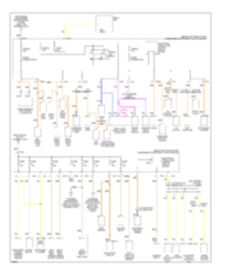
Power Distribution Wiring Diagram (4 of 6) for Hyundai XG350 L 2004
List of elements for Power Distribution Wiring Diagram (4 of 6) for Hyundai XG350 L 2004:
- (behind left end of dash) passenger compartment junction block
- (not used)
- (on left front of engine compartment) engine compartment junction block
- (w/ trip computer)
- (w/o trip computer)
- A11
- Aqs sensor
- Auto light sensor
- C12
- Canister close valve
- Digital clock
- Driver seat buckle switch
- Drl control module
- E11
- E12
- Electronic time & alarm control module (etacm)
- Ets relay
- From egr fuse, 15a (diagram 3 of 6)
- From engine compartment junction block (abs fuse, 10a) (diagram 2 of 6)
- From engine compartment junction block, (fuse 11, 15a) (diagram 5 of 6)
- From engine compartment junction block, (fuse 5, 10a) (diagram 5 of 6)
- Fuse 10a
- Fuse 21 10a
- Fuse 22 15a
- Generator
- Hazard switch
- Headlight relay (high)
- Headlight relay (low-lh)
- Hid head lamp relay
- I/p-b
- I/p-d
- I/p-g
- I/p-h
- I/p-j
- I/p-k
- I/p-l
- I18-2
- Immobilizer control module
- Instrument cluster
- Jc01
- Jc01 a6
- Je01
- Jm09
- Left head lamp leveling actuator
- M33-3
- Nca
- Oxygen sensor (bank 1/ sensor 1)
- Oxygen sensor (bank 2/ sensor 1)
- Oxygen sensor fuse 15a
- Passenger presence detection sensor
- Passenger seat buckle switch
- Pnk
- Pre- excitation resistor
- Relay box
- Right head lamp leveling actuator
- Srs control module
- Stop lamp failure relay
- Tcs switch
- Transaxle range switch
- Trip computer
- Vehicle speed sensor
- Washer motor
- Wiper motor
- Wiper motor relay
Power Distribution Wiring Diagram (5 of 6) for Hyundai XG350 L 2004
List of elements for Power Distribution Wiring Diagram (5 of 6) for Hyundai XG350 L 2004:
- (behind left end of dash) passenger compartment junction block
- (left center of dash) j/c i20
- (not used)
- (w/o home link) (w/ home link)
- A/c control module
- A/c control module (automatic a/c)
- A/c switch
- A/c switch (manual a/c)
- Assister door module
- Audio
- Auto headlamp levelling sensor
- Auto- matic a/c
- Automatic a/c manual a/c
- Blower relay
- Cruise switch
- Digital clock
- Door warning & ignition key illumination
- Driver door module
- Electrical chrome mirror (w/ home link)
- Electrical control mirror
- Electronic power steering control module
- Electronic time & alarm control module (etacm)
- Ets relay
- From engine compartment junction block, power fuse 2, 30a (diagram 3 of 6)
- From ignition switch (diagram 1 of 6)
- Fuel filler door & trunk lid switch
- Fuse 10a
- Fuse 15a
- Fuse 20 10a
- Fuse 20a
- Fuse 24 20a
- Fuse 25 10a
- Fuse 4 15a
- I/p-a
- I/p-d
- I/p-e
- I/p-g
- I/p-h
- I/p-j
- I/p-k
- I/p-m
- I/p-p
- I17-1
- I18-1
- I18-2
- Immobilizer control module
- Ims control module
- Instrument cluster
- Left foot lamp
- Left front door lamp
- Left front seat warmer switch
- Left trunk room lamp
- M110-4
- M33-3
- Manual a/c
- Map lamp
- Mode actuator
- Multipurpose check connector
- Nca
- Overhead console lamp
- Rain sensor
- Rain sensor relay
- Red
- Relay box
- Right foot lamp
- Right front door lamp
- Right front seat warmer switch
- Right trunk room lamp
- Room lamp
- Short connector "b"
- Short connector a
- Sunroof relay
- Tempe- rature switch
- To engine compartment junction block, headlight relay (high) (diagram 4 of 6)
- To engine compartment junction block, wiper motor relay (diagram 4 of 6)
- Trip computer
- Trunk lid relay
- Trunk lid solenoid
- W/ sunroof
- W/ trip computer
- W/o sunroof
- W/o trip computer
Power Distribution Wiring Diagram (6 of 6) for Hyundai XG350 L 2004
List of elements for Power Distribution Wiring Diagram (6 of 6) for Hyundai XG350 L 2004:
- (not used)
- (on left front of engine compartment) engine compartment junction block
- A/c control module (automatic a/c only)
- A/c switch (manual a/c only)
- A/t control relay
- A/t fuse 20a
- Assister door module
- Audio
- C11
- C44-2
- Cruise switch
- Driver door module
- Drl control module
- Drl fuse 15a
- Ecm fuse 10a
- Ets control module
- Exterior lights system
- Fog lamp fuse 15a
- From main fuse, 30a (diagram 2 of 6)
- Front cigarette lighter
- Front fog lamp relay
- Fuel pump fuse 20a
- Fuse 26 10a
- Fuse 31 10a
- Generator
- Glove box illumination
- Hazard switch
- Head lamp (hi) fuse 15a
- Head lamp (lo-lh) fuse 15a
- Head lamp (low-rh) fuse 15a
- Head lamp washer fuse 20a
- Headlamp relay (high)
- Headlamp relay (low-lh)
- Hid headlamp relay
- I/p-a
- I/p-b
- I/p-d
- I/p-e
- I/p-h
- I/p-k
- I/p-p
- I17-1
- I18-2
- Ims switch
- Instrument cluster
- J/c i29 (right center of dash)
- J/c m37 (upper right side of dash)
- J/c m71 (under left front seat)
- Jc01
- Je01
- Je01 d12
- Jm09
- Jm09 c8
- Left front seat warmer switch
- Left license lamp
- Left rear combination lamp
- Left rear power window switch
- Left side marker lamp
- Left turn signal lamp
- Nca
- Passenger compartment junction block (behind left end of dash)
- Pcm
- Rear side marker lamp
- Red
- Rheostat
- Right front seat warmer switch
- Right license lamp
- Right rear combination lamp
- Right rear power window switch
- Right side marker lamp
- Right turn signal lamp
- Short connector c
- Siren
- Sport mode & shift limit switch
- Tail lamp fuse 20a
- Taillamp relay
- Tcs switch
- To power fuse 1, 30a (diagram 3 of 6)
- Trip computer