ANTI-THEFT
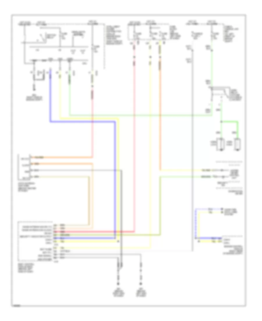
Anti-theft Wiring Diagram for Nissan Quest SL 2004
List of elements for Anti-theft Wiring Diagram for Nissan Quest SL 2004:
- +ig
- 13p
- Bat (f/l)
- Bat (fuse)
- Body control module (bcm) (behind left side of dash)
- Can h
- Can l
- Can-h
- Can-l
- Clock
- Combination meter
- Computer data lines system
- Cpu
- E121
- E124
- E24 (right side of engine compt)
- E30
- Engine control module (right rear of engine compt)
- Fuse & fusible link box (at left front of engine compt)
- Fuse 10a
- Fuse 15a
- Fuse block (j/b) (behind left side of dash)
- Fusible link j 50a
- G57 (behind left end of dash)
- G61 (behind right end of dash)
- Gnd
- Gnd (power)
- Gnd (signal)
- H/lp hi
- H/lp lo
- Headlights system
- Horn (high)
- Horn (low)
- Horn relay (in fuse & fusible link box)
- Horn rly
- Hot at all times
- Hot in on and start
- Ign sw
- Ignition relay
- Immob antenna sig (clock)
- Immob antenna sig (rx,tx)
- Intelligent power distribution module engine room (ipdm e/r) (right side of engine compt)
- M18
- M19
- Nats antenna amplifier (behind center of dash)
- Red
- Rx,tx
- Security ind
- Security indicator output
- Unified meter control unit
- Vb (12v)
 English