ENGINE PERFORMANCE
3.5L
3.5L, Engine Performance Wiring Diagram (1 of 4) for Nissan Quest SL 2004

List of elements for 3.5L, Engine Performance Wiring Diagram (1 of 4) for Nissan Quest SL 2004:
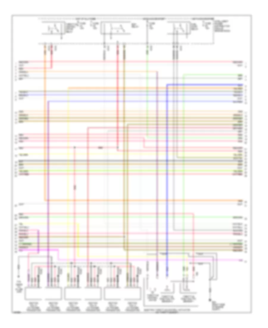
3.5L, Engine Performance Wiring Diagram (2 of 4) for Nissan Quest SL 2004
List of elements for 3.5L, Engine Performance Wiring Diagram (2 of 4) for Nissan Quest SL 2004:
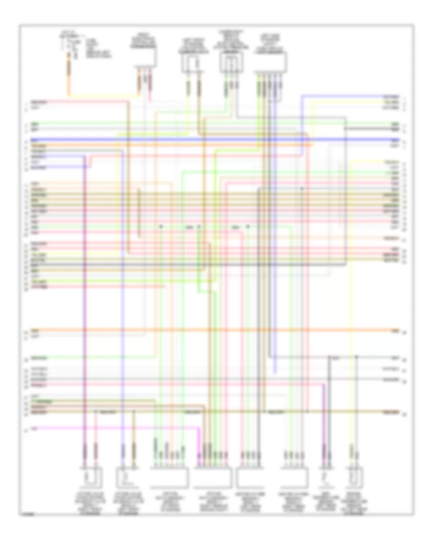
3.5L, Engine Performance Wiring Diagram (3 of 4) for Nissan Quest SL 2004
List of elements for 3.5L, Engine Performance Wiring Diagram (3 of 4) for Nissan Quest SL 2004:
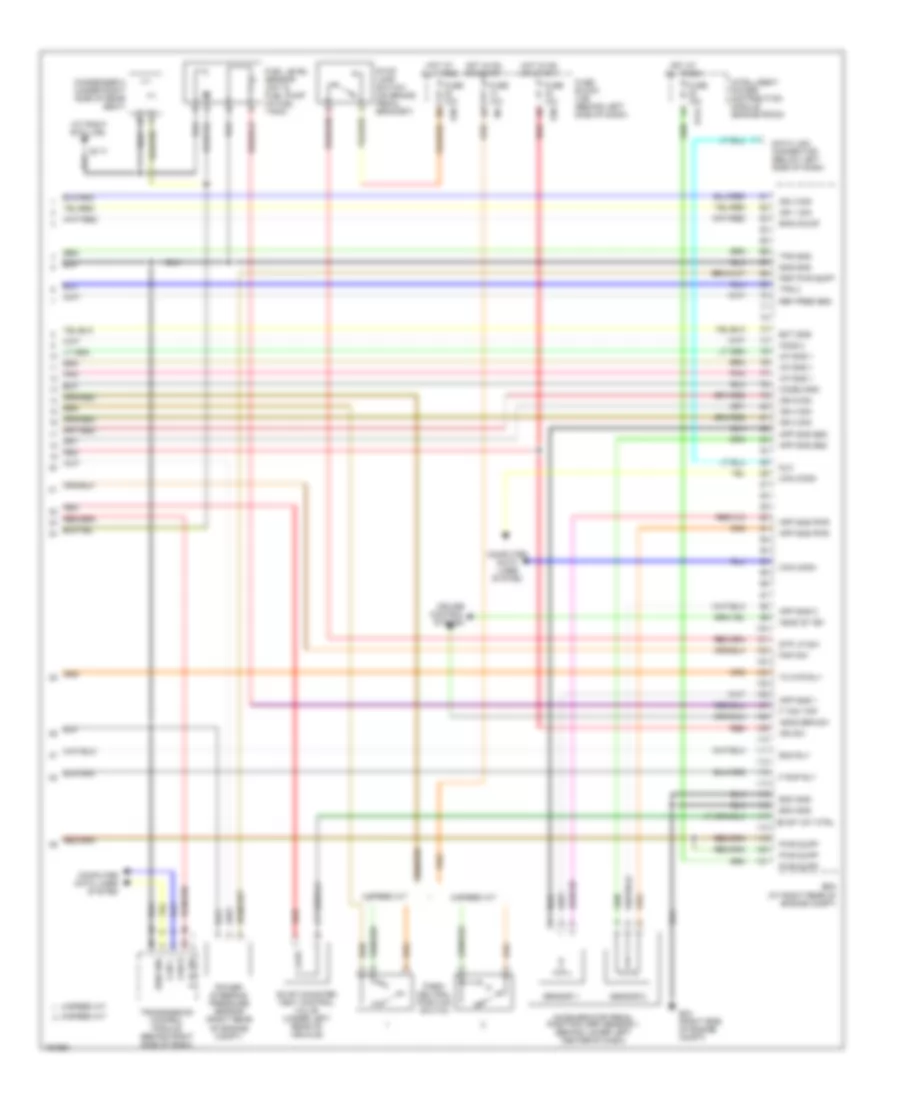
3.5L, Engine Performance Wiring Diagram (4 of 4) for Nissan Quest SL 2004
List of elements for 3.5L, Engine Performance Wiring Diagram (4 of 4) for Nissan Quest SL 2004: