ANTI-THEFT
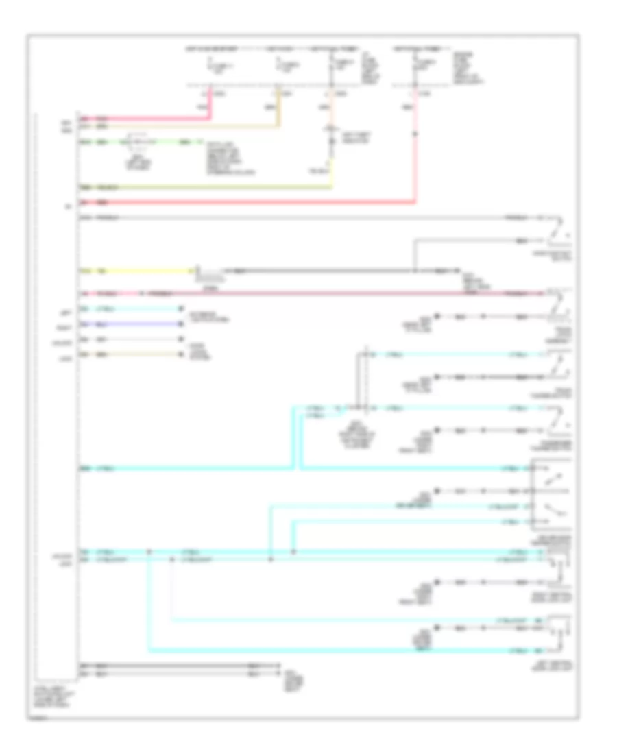
Anti-theft Wiring Diagram for Suzuki Verona 2006
List of elements for Anti-theft Wiring Diagram for Suzuki Verona 2006:
- A10
- A11
- A15
- Anti-theft indicator
- B19
- B20
- B30
- C106
- C12
- C201
- C202
- C205
- Data link connector (below left side of dash, right of steering column)
- Door locks system
- Driver door temper switch
- Engine fuse block (left front of eng compt)
- Exterior lights system
- Fuse 11 10a
- Fuse 21 10a
- Fuse 5 60a
- Fuse 6 10a
- G101 (behind left head lamp)
- G301 (under driver seat)
- G302 (under right front seat)
- G303 (near left "c" pillar)
- Hood contact switch
- Hot at all times
- Hot in on
- Hot in on or start
- I/p fuse block (left end of dash)
- Ign1
- Ign2
- Intelligent switching unit (lower left side of dash)
- Left
- Left central door lock unit
- Lock
- Passenger tamper switch
- Pnk
- Red
- Right
- Right central door lock unit
- S201 (left end of dash)
- S301 (behind right side of instrument cluster)
- Siren
- Trunk latch assembly
- Trunk tamper switch
- Unlock
 English