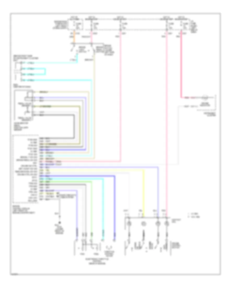
CRUISE CONTROL
Cruise Control Wiring Diagram for Suzuki Verona 2006
List of elements for Cruise Control Wiring Diagram for Suzuki Verona 2006:
- (behind right side of instrument cluster) s301
- 5v ref
- A40
- A53
- A54
- A55
- A56
- A57
- A58
- A59
- Accelerator pedal position (app) sensor
- Brake light switch
- Brake lt sw sig
- Brake pedal sw sig
- Brake pedal switch
- Brake switch (lower left side of dash)
- C102
- C11
- C14
- C201
- C202
- Can hi
- Can low
- Coast set/
- Computer data lines system
- Contact coil
- Cruise
- Cruise control switch
- Cruise ctrl sw sig
- Cruise ind ctrl
- Cruise indicator
- Ecu_gnd
- Electronic throttle control (rear of engine)
- Engine control module (left front of engine compartment)
- Engine room fuse block (left front of eng compt)
- Etc1
- Etc2
- Fuse 10a
- Fuse 15a
- Fuse 20a
- Hot at all times
- Hot in on or start
- I/p fuse block (left end of dash)
- Ign1
- Instrument cluster
- K23
- K24
- K36
- K49
- K53
- K60
- K61
- K71
- K72
- K77
- K78
- K83
- Nca
- Pedal valve sensor 1
- Pedal valve sensor 2
- Pnk
- Pvs1 gnd
- Pvs1 sig
- Pvs2 gnd
- Pvs2 sig
- Resume accel
- Resume/accel sw sig
- S203 (center of dash)
- Set coast sw sig
- Switch on
- Throttle control motor
- Tps gnd
- Tps1
- Tps1 sig
- Tps2
- Tps2 sig
- W/ arc
- W/o arc
 English