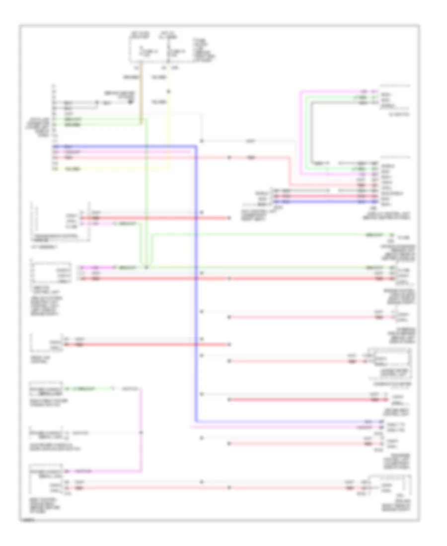
COMPUTER DATA LINES
Computer Data Lines Wiring Diagram for Nissan Armada LE 2004
List of elements for Computer Data Lines Wiring Diagram for Nissan Armada LE 2004:
- (behind center of dash) m61
- A/t assembly
- Abs actuator & electric unit (control unit) (left side of engine compt)
- Abs/tcs control unit
- Air bag diagnosis sensor unit (below rear of center console)
- Av switch
- B152
- Body control module (bcm) (behind center of dash)
- Bus +
- Bus -
- Bus shield
- Can-h
- Can-l
- Cnslt rx
- Cnslt tx
- Combination meter
- Cpu
- Data link connector (lower left side of dash)
- Diag-k
- Display control unit (behind center of dash)
- Driver seat control unit
- E122
- E142
- Engine control module (ecm) (right side of engine compt)
- Front air control
- Fuse 12 10a
- Fuse 19 10a
- Fuse block (j/b) (behind right end of dash)
- Hot at all times
- Hot in on or start
- Ipdm e/r (right rear of engine compt)
- K-line
- M18
- M35
- M39
- M95
- Main power window & door lock/unlock switch
- Navi control unit (under right front seat)
- Nca
- Pnk
- Power window serial link
- Red
- Right front power window switch
- Shield
- Steering angle sensor (behind left side of dash)
- Transfer control unit (lower right side of dash)
- Transmission control module
- Unified meter control unit
 English