WARNING SYSTEMS
Warning Systems Wiring Diagram for Nissan Armada LE 2004
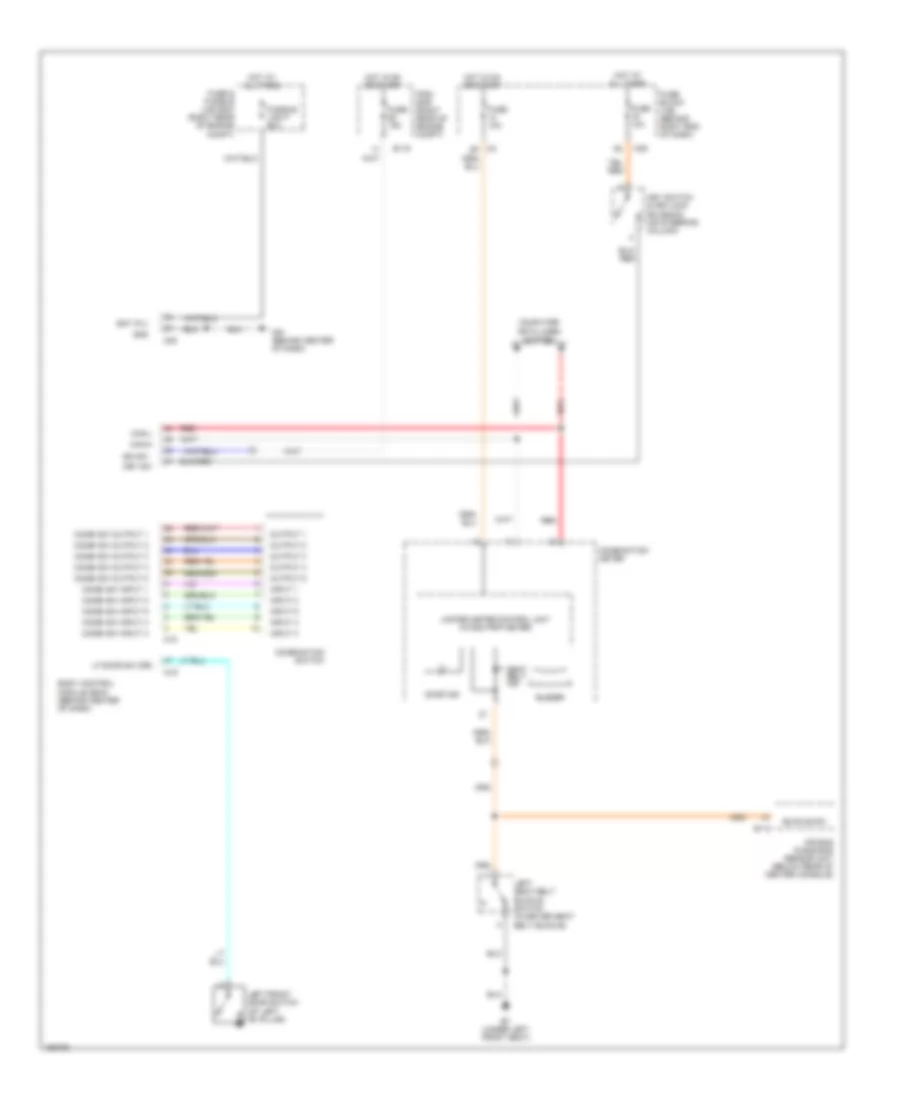
List of elements for Warning Systems Wiring Diagram for Nissan Armada LE 2004:
- Air bag diagnosis sensor unit (below rear of center console)
- B113
- B7 (under left front seat)
- Bat (f/l)
- Body control module (bcm) (behind center of dash)
- Buckle sw
- Buzzer
- Can-h
- Can-l
- Combi sw input 1
- Combi sw input 2
- Combi sw input 3
- Combi sw input 4
- Combi sw input 5
- Combi sw output 1
- Combi sw output 2
- Combi sw output 3
- Combi sw output 4
- Combi sw output 5
- Combination meter
- Combination switch
- Computer data lines system
- Door ind
- E119
- Fuse & fusible link box (right rear of engine compt)
- Fuse 10a
- Fuse 15a
- Fuse block (j/b) (behind right end of dash)
- Fusible link f 50a
- Gnd
- Hot at all times
- Hot in on or start
- Ign sw
- Input 1
- Input 2
- Input 3
- Input 4
- Input 5
- Ipdm (e/r) (right rear of engine compt)
- Key sw
- Key switch & keylock solenoid (on steering column)
- Left front door switch (at left "b" pillar)
- Left seat belt buckle switch (in driver seat belt buckle)
- Lf door sw (dr)
- M18
- M19
- M20
- M39
- M61 (behind center of dash)
- Output 1
- Output 2
- Output 3
- Output 4
- Output 5
- Red
- Seat belt ind
- Unified meter control unit (w/odo/trip meter)
 English